Showing posts with label supply. Show all posts

Thursday, November 13, 2014

12V fixed voltage power supply circuit diagram

Here this circuit diagram is for +12V regulated (fixed voltage) DC power supply. These power supply circuit diagram is ideal for an average current requirement of  1Amp. This  circuit is based on IC LM7812. It is a 3-terminal (+ve) voltage regulator IC. It has short circuit  protection , thermal overload protection.  LM7812 IC is from LM78XX series. The LM78XX series IC is  positive voltage regulator IC for different voltage requirements, for example LM7805 IC is made for 5 volt fixed output voltage . There is LM79XX IC series for negative voltage .

Circuit diagram of 12V fixed voltage power supply
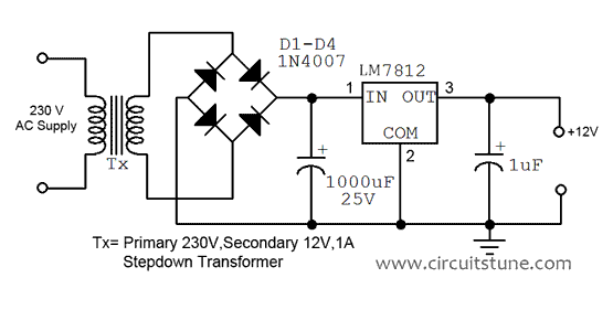

A transformer(Tx=Primary 230 Volt, Secondary 12 Volt , 1Amp step down transformer) is used to covert 230V to 12V from mains. Here used a bridge rectifier made by four  1N4007 or 1N4003 diode to convert AC to DC . The filtering capacitor 1000uF,25V is used to reduce the ripple and  get a smooth DC voltage. This circuit is very easy to build. For good performance input  voltage should be greater than 12Volt in pin-1 of IC LM7812. Use a heat sink to IC LM7812 for safeguarding it  from overheating.


12
Fig: 12V power supply circuit diagram
Read More..

Friday, November 7, 2014

LM723 Variable Power Supply with Over Current Protection

The circuit design was intended to create an adjustable power supply over a range of 1.3V to 12.2V at 1A and be able to provide protection for over-current by utilizing LM723 regulator.


 Terminology
  • LM723 – a positive NPN standard voltage regulator mainly designed for series regulator applications which can be utilized for both foldback and linear current limiting due to its very low standby current drain circuit
  • Voltage Regulator – an electrical or electronic device created for the purpose of maintaining a constant voltage level of a power source within the suitable limits
  • 2N3055 – a complementary Silicon Epitaxial-Base planar NPN transistor mounted in Jedec TO-3 metal case for use as power transistor
Circuit Explanation
The integrated voltage regulator LM723 will supply 150 mA of output currents but any desired load current can be provided by adding external transistors for output currents in excess of 10A. This can be used as a linear or switching regulator since its output voltage can be adjusted from 2 Volts to 37 Volts while the input voltage can be at 40 Volts maximum. The range of variations of input voltage and load current can be kept at constant using this voltage regulator.

In this design, the DIL14 plastic packaged LM723 performs with 9.5V to 40V input DC voltage while having an output voltage that is not more then 6V to 7V below the input will lead to 150 mA current source from  the IC. The difference between the input and the output DC voltage plus the current is proportional to the amount power being dissipated by the transistor T1 as it accepts all the current brought by the load, thus requiring a heatsink with a heat conductive value of 5K/W. T1 is made from 2N3055 which is intended for series and shunt regulators, for output stages and high fidelity amplifiers, and for power switching circuits. The output stage of the integrated circuit will be less loaded when an external pass transistor is used which will conduct at emitter-follower mode. This will in turn cause T1 to conduct at base-emitter mode thereby producing a major resistance in the IC.

Both ceramic capacitors must be positioned closer to the integrated circuit to prevent undesired oscillations, which the LM723 is prone to, since ceramic capacitors have high frequency coefficient of dissipation. Having these capacitors directly soldered would be too much for the IC since the operating temperature of the IC is in the range of -55ᵒC to +125ᵒC

Application
Voltage regulators are used for several advantages in areas where uncontrolled voltage varies more than the accepted voltage of equipment which could be harmful and damaging. In motor vehicles, it matches the charging requirements of the battery and electrical load to the output voltage of the generator by rapidly switching from one to another of three circuit states using a dual pole switch loaded with spring. To keep a recommended range of voltage supplied to a consumer, regulators are used by alternating current distribution feeders or large scale power distributions or substations. This is useful in protecting the equipment using electricity by minimizing the variations in voltage.  The two types of regulators being used are step regulators where the current supply is controlled and the induction regulator where an induction motor adjust the voltage by supplying a secondary which smoothens the feeder line’s current variations.
The LM723 voltage regulators are widely used for wide range of applications such as a temperature controller, a current regulator, or a shunt regulator. Also, DC power supplies in electronic equipment are using voltage regulators.

Source:zen22142.zen.co.uk/Circuits/Power/723psu.htm
Read More..

Sunday, October 5, 2014

5 to 15V 400mA Regulated Power Supply

5 to 15V 400mA Regulated Power Supply

This project is a simple DC regulated power supply that has a variable DC voltage range from 5V to 15V. It can supply current up to a 400mA to power the various circuits for your electronic projects. The voltage output is varied by using the potentiometer VR1. In this circuit, the input line power supply is designed for 240VAC. If 110VAC input is used, change the ratings of the varistor to 150VAC and the transformer ratio to 110V/12V.

Fuse F1 is used as a protection in case there is any short circuit in the circuit. Varistor V1 is connected in parallel to the input of the line voltage to clamp the surge voltage from the line to a reasonable level that helps to protect the transformer and other circuitry. Once the voltage level surge to a high level beyond the ability of the varistor to absorb it, fuse F1 or varistor V1 or both will burn. If this circuit failed after a period of operation, check that the fuse and the varistor are still in good condition or else replace them.

Diodes D1, D2, D3 and D4 are used to rectify the 12VAC voltage to DC voltage. Electrolytic capacitor E1 is used as a smoothing capacitor to reduce the ripple of the DC voltage. The DC voltage is fed into the input of 7805 regulator where the output DC voltage is obtained. Changing the value of VR1 will change the output of the DC voltage. Capacitor C1 is used to filter out high frequency component from the power supply.
Read More..

Wednesday, September 10, 2014

9 Volt DC Power Supply Using LM317 Regulator

There are many ways to obtain a very stable voltage 9VDC which has very minimal distortion. If you really love in the audio field, you must have a power supply at the level of the OP Amp should be free from hum. Use of Power Supply which has a higher stabilization and free of humming and buzzing frequently encountered in the use of communication tools such as Handy-talkie and radio transmitters.


Power
To overcome the above problem, we have to provide the filters on the power supply using IC regulator. You can use the LM 7809 or you can also use the regulator IC LM 317. This regulator has advantages over the use of IC 78XX. LM317 has a nature that is at the Gate (no.1 feet) can be tuned to provide feedback which is inversely proportional to the value of R (resistor). The R value can affect the output voltage on pin 2(V-out), pin 3 as input (V-in). The function R can be replaced with a variable resistor, but you must have an indicator meter or AVO meter to ensure that the output voltage is true 9 Volt. If youve found your desired voltage, for example 9VDC, then you can connect to the component that you want to turn on. So first set the output voltage using a volt meter before connecting to the equipment to be you turn on.
Power
KA317 / LM317 is a Three Terminal Positive Adjustable Regulator integrated schema, the monolithic characteristic adjustable positive voltage regulator designed to supply more than 1.5 A of load current with output voltage can be adjusted with a range capability 1.2 V of up to 37 V. This tool will work for internal current limiting, thermal shut-down and securing the compensation scope. You have to use aluminum as an additional cooling.

This schema will deliver 9V regulated DC voltage at maximum current of about 1A. The schema uses a transformer with a secondary output voltage 15-24V AC/1A. To give input in Primary of transformer, it’s dependent electrical conduit installation in your home. If the mains voltage 110V, then you have to find a 110V in transformer primary voltage. For the diode, you can use 4 pieces diodes 1N4002 (1A rectifier diode) or better by using a diode bridge 2A.
Power
9 Volt DC Power Supply Using LM317 Regulator
In the following schema scheme, we can see the typical basic application into obtaining voltage can be adjusted.
Read More..

Saturday, September 6, 2014

5 to 15V 400mA Regulated Power Supply

5 to 15V 400mA Regulated Power Supply

This project is a simple DC regulated power supply that has a variable DC voltage range from 5V to 15V. It can supply current up to a 400mA to power the various diagram for your electronic projects. The voltage output is varied by using the potentiometer VR1. In this schema, the input line power supply is designed for 240VAC. If 110VAC input is used, change the ratings of the varistor to 150VAC and the transformer ratio to 110V/12V.

Fuse F1 is used as a protection in case there is any short schema in the schema. Varistor V1 is connected in parallel to the input of the line voltage to clamp the surge voltage from the line to a reasonable level that helps to protect the transformer and other schemary. Once the voltage level surge to a high level beyond the ability of the varistor to absorb it, fuse F1 or varistor V1 or both will burn. If this schema failed after a period of operation, check that the fuse and the varistor are still in good condition or else replace them.

Diodes D1, D2, D3 and D4 are used to rectify the 12VAC voltage to DC voltage. Electrolytic capacitor E1 is used as a smoothing capacitor to reduce the ripple of the DC voltage. The DC voltage is fed into the input of 7805 regulator where the output DC voltage is obtained. Changing the value of VR1 will change the output of the DC voltage. Capacitor C1 is used to filter out high frequency component from the power supply.
Read More..

Friday, September 5, 2014

1 3 12V Small Variable Power Supply


This is a small variable power supply delivers adjustable output voltage of 1.3v-12v. The current output determined by R3. With current setting (see part list), it will deliver current output about 1A.


Detail Specification:
Output (approximate values):

Vmin = (R4 + R5) / (R5*1.3)
Vmax = (7.15 / R5) * (R4 + R5)
Imax = 0.65/R3
Max. Power on R3: 0.42/R3
Min. Input DC Voltage (pin 12 to pin 7): Vmax + 5

Parts List
B1 = 40V/2.5A
R1 = 1k ohm
R2 = Potensiometer 5k ohm
R3 = 0.56R/2W
R4 = 3.3k ohm
R5 = 4.7k ohm
C1 = 2200uF (3300uF even better)
C2 = 4.7uF
C3 = 100nF
C4 = 1nF
C5 = 330nF
C6 = 100uF
D1 = Green LED
D2 = 1N4003
F1 = 0.2A F
F2 = 2A M
IC1 = LM723 (in a DIL14 plastic package)
S1 = 250V/1A
T1 = 2N3055 on a heatsink 5K/W
TR1 = 220V/17V/1.5

R2 sets the output voltage. The maximum current is decided by the value of R3: the over-current protection schemary inside the LM723 senses the voltage across R3 and starts shutting the output stage off as soon as this voltage approaches 0.65 V. This way the current through R3 can never exceed 0.65/R3, even if the output is shorted.

C3 and C4, both ceramic, must be placed as close as possible to the integrated schema, because the LM723 can be prone to unwanted oscillations. It is not an overkill to solder them directly (and very carefully) to the pins of the IC. All other connections should also be kept short.

The LM723 works with input DC voltages from 9.5 to 40 V and the IC itself can source some 150 mA if the output voltage is not more than 6-7 V below the input. When an external pass transistor is used (in the usual emitter-follower mode), the base-emitter junction of T1 represents a significant resistance and the integrated diagram output stage is relatively lightly loaded. All the current drawn by the load passes through T1 and it dissipates an amount of power that is directly proportional to the current and the difference between the input and the output DC voltage.
Read More..

Wednesday, September 3, 2014

Simple Dual Regulated Power Supply Wiring diagram Schematic

This is a Simple Dual Regulated Power Supply Circuit Diagram. A regulated power supply is an embedded schema; it converts unregulated AC into a constant DC. With the help of a rectifier it converts AC supply into DC. In this schema, the 7815 regulates the positive supply, and the 7915 regulates the negative supply. The transformer should have a primary rating of 240/220 volts for europe, or 120 volts for North America. The centre tapped secondary coil should be rated about 18 volts at 1 amp or higher, allowing for losses in the regulator. An application for this type of schema would be for a small regulated bench power supply. 


Simple Dual Regulated Power Supply Circuit Diagram

Simple

Read More..

Fixed Voltage Power Supply

The fixed voltage power supply is useful in applications where an adjustable output is not required. This supply is simple, but very flexable as the voltage it outputs is dependant only on the regulator and transformer you choose. The maximum output current is 1.5A. Fixed Voltage Power Supply Circuits diagram :   Parts : Part    Total     Description C1           1       2200uF 35V Electrolytic Capacitor C2, C4     2       0.1uF Ceramic Disc Capacitor C3           3       10uF 35V Electrolytic Capacitor

D1, D2    1        1N4007 Silicon Diode

BR1        1        2A 30V Bridge Rectifier

U1          1        Regulator (See Notes) T1          1        Transformer (See Notes) S1          1        SPST 2 Amp Switch F1          1        2A 250V Fuse and Holder  Misc      1        Heatsink For U1, Line Cord, Case, Wire  

Notes :

  1. Since this project operates from 120 (or 220, or 240, etc.) volts AC, it MUST be built inside a case.
  2. U1 will reauire a heatsink.
  3. You will need to choose T1 and U1 to match the voltage you want. Use the table below as a reference.

Read More..

Sunday, August 31, 2014

Simple Power supply without transformer

Simple
This circuit has a voltage output of about 12 volts with 20mA current voltage. And this series of works using capacitive reactance and resistance are not using, this will reduce the heat on the circuit.


To be safe when there is a short-circuit series, always use a fuse on the input voltage is 220V. Here is a series of power supply without a simple transfomer.
Power
Power supply Circuit
Part List
R1 - 1.8K 1W
R2 - 100Ω
C1 - 0.47µF 400V
C2 - 1000µF 50V
D1 - 1N4007
D2 - 1N4007
D3 - 1N4007
D4 - 1N4007
ZD1 - 16V Zener Diode
ZD2 - 16V Zener Diode
ZD3 - 12V Zener Diode
Read More..

Tuesday, August 26, 2014

Adapter power supply and charger circuit

Basically adapter, power supply and charger circuit has a similar construction which consists of a transformer, rectifier (rectifier) and smoothing the voltage. For there is usually an additional power supply voltage stabilizer of voltage regulator IC LM series 78XX or 79XX .
Below is a schematic circuit adapter, power supply, or battery charger (for gadgets, mobile phones, MP4player, smartphone) that is equipped with a 5V voltage stabilizer:

adapter,
Adapter, power supply and charger circuit

Read More..

Saturday, August 23, 2014

Wiring diagram Schematic of Photocell Power Supply MAX630

This Circuit Diagram of Photocell Power Supply (MAX630) delivers either 4.8 or 7.2 V regulated at 15 mA with a 3-V input from a bank of photocells. R1 should be 453 k? for a 7.2-V output and 274 k? for a 4.8-Vdc output. Regulator efficiency is around 70%. This should be considered when selecting suitable solar cells.

Circuit Diagram of Photocell Power Supply (MAX630)

Circuit

Read More..

Friday, August 22, 2014

Power Supply 1 2 12V 1A with low voltage LED Indicator

Power

This power supply can provide output voltage 1.2V - 12 with maximal output current is 1A, low voltage LED indicator added in this schematic diagram. The indicator part includes three diodes and one LED. For example you are charging a battery, you can observe the charge status at that moment. Another advantage of this schema, when the drawn current exceeds 1A (practically 0.85A), the current protector in LM317 intervenes and LED indicator warns you about the very low output voltage.
Read More..

Simple Uninterrupted Power Supply in an IC

The Uninterrupted Power Supply in an IC . Cymbet Corporation announced the availability of the EnerChip™ CC CBC3105 smart solid state battery. The CBC3105 combines the award winning EnerChip battery with integrated input power conversion, battery management and regulated output capabilities. The Cymbet EnerChip™ CC is a smart rechargeable solid state battery Uninterrupted Power Supply (UPS in a Chip™) that provides power backup to microelectronic devices when main power fails. The EnerChip CC provides power supply monitoring and switches over to the internal solid state backup battery when the supply drops below a set threshold. The EnerChip CC product family can provide anywhere from several hours to several weeks of backup time.

 Simple Uninterrupted Power Supply in an IC Circuit Diagram
Simple
 
The CBC3105 is an ideal solution for design engineers who need a compact device to back-up a Real Time Clock or Microcontroller during power failure where coin cell batteries or super caps will not work due to size, reliability, no battery doors, no battery replacement, battery disposal issues, or need for life-of-product power. The CBC3105 uses surface mount/reflow solder assembly and is RoHS tested-compliant. 

The EnerChip CC device family can accomplish all this in a footprint as small as the CBC3105 4mm x 5mm x 0.9mm package that is priced as low as $0.50 in high volumes. The EnerChip CC CBC3112 and CBC3150 provide even more energy storage in similar small footprint packages. The CBC3105 can be purchased at Avnet, Avnet Abacus, Avnet Asia, Digi-Key, Mouser and Farnell.
Easy-to-Use Evaluation Kits for Power Backup Applications
Cymbet makes it easy to design EnerChips into new products by offering two EnerChip CC evaluation kits:
  • CBC-EVAL-05 EnerChip CC Evaluation Kit which contains everything needed to test EnerChip 12uAh and 50uAh thin film batteries, EnerChip CC CBC3112 and CBC3150 batteries with Integrated Battery Management, and to test multiple batteries in parallel. This kit will also include a CBC3105 evaluation board for experimenting with this device.
  • CBC-EVAL-06 Real-Time-Clock Evaluation Kit: includes a Microcrystal NV2123 Real-Time Clock device and a CBC3112 EnerChip CC for battery backup. This kit also includes a Windows based Graphical User Interface to set the clock & test operation in RTC back up and count-down modes.
Visit Cymbet at Design West/ESC Booth 2330 for UPS in a Chip Demos
At booth 2330 at Design West/ESC 2012 at the San Jose Convention Center March 27-29, 2012, Cymbet will demonstrate tiny footprint power backup solutions that give designers the ability to create optimized products. By providing all the functions of a UPS system in a single chip, the EnerChip CC batteries enable a new class of products that utilize life-of-product energy storage.
Read More..

Wednesday, August 20, 2014

General Purpose Power supply Wiring diagram Schematic

The General Purpose Power supply Circuit Diagram supply 6-66 can be used for supply output voltages from 1 to 35 V. The line transformer should be selected to give about1.4 times the desired output voltage from the positive side of filter capacitor C1 to ground. Potentiometer R2 sets the output voltage to the desired value by adjusting the reference input. Rsc is the current limit set resistor.Its value is calculated as: For example, if the maximum current output is to be 1 A, Rsc ~ 0.65/1.0 ~ 0.65 0. The 1-KO resistor, Rs, is a light-loaded resistor designed to improve the no-load stability of the supply. 

General Purpose Power supply Circuit Diagram

General

Read More..

Monday, August 18, 2014

Simple Positive And Negative Voltage Power Supply Wiring diagram Schematic

This Simple Positive And Negative Voltage Power Supply Circuit Diagram provides a precision voltage source that can be adjusted through zero to positive and negative voltages, which eliminates reversing connections on the power supply. Also, it is possible to get exactly 0 V, without some offset. As to how this schema works, first consider the -1 V/V to +1 V/V linear gain-control amp (see the figure). A Burr-Brown INA105 difference amp is used in a unity-gain inverting amp configuration. 

 Positive And Negative Voltage Power Supply Circuit Diagram

Simple


A potentiometer is connected between the input and ground. The pot`s slider is connected to the noninverting input of the unity-gain amp; this input is typically connected to ground. With the slider at the bottom of the pot, the schema is a normal-precision unity-gain inverting amp with a gain of -1.0 V/V ± 0.01% maximum. 

With the slider at the top of the pot, the schema is a normal-precision voltage follower with a gain of ± 1.0 V/V ± 0.001% maximum. With the slider in the center, there`s equal positive and negative gain for a net gain of 0 V/V. The accuracy between the top and the bottom will usually be limited by the accuracy of the pot.

Source Simple Positive And Negative Voltage Power Supply Circuit Diagram
Read More..

Sunday, August 17, 2014

Auxiliary Negative Dc Supply Wiring diagram Schematic

In this Auxiliary Negative Dc Supply Circuit Diagram, IC1 (CD4009) is used as a square-wave oscillator at approximately 25 kHz. CI and Rl set this frequency. C2, Dl, D2, and C3 form a p-p rectifier, which outputs about -3.5 Vdc. This schema should be useful where a small negative dc supply is required, but only positive dc voltages are available.

Auxiliary Negative Dc Supply Circuit Diagram

Auxiliary

Read More..

Saturday, August 16, 2014

0 to 3V Adjustable Output Power Supply

0 to 3V Adjustable Output  Power Supply schema diagram

This is an LM317 based adjustable voltage regulator with a maximum output of 3V and 1.5A. The output voltage depends on the VIN, R1 and R2 values, so the schema can be modified to use with a maximum output of greater than 3V. The maximum current output is also independent of the schema design, it is related to the package options. In this schema, LM317T, which is capable of transferring up to 1.5A, is used.

Since the internal reference voltage of the LM317 regulator is 1.25V, the output voltage can be also minimally 1.25V. One way to overcome this problem is using a reference voltage source built on two diodes. But this approach is mostly suitable for 1.5V to 15V regulators since the sensitivity becomes poor for the low voltage outputs less than 1.5 . On the other hand, diodes have temperature dependent forward voltages.

www.schema-projects.com

Read More..

Thursday, August 14, 2014

Build a 13KV High voltage Power supply Wiring diagram Schematic

This 13KV High voltage Power supply Circuit Diagram has an inverter around Q1 that supplies 150-V pulses to the converter of SCR1 and C2. The output of ?2 is a 4.5-kV pulse that is multiplied by the voltage-tripler network (right) to produce 13.5 kV. R1 is a 3k to 500K CT transistor audio transforfiler, L2 is a flash tube trigger transformer with a 6-kV secondary. 


13KV High voltage Power supply Circuit Diagram

13KV High voltage Power supply Circuit Diagram

Read More..

LM338 Power Supply 13 8V 5A

This ac to dc power supply can output 5A in continous operation and 12A peak current. This kind of dc power supplies uses a PCB so you can use two case types for IC1, TO-220 or TO-3. The regulation of this 12 volt power supply is made with TR1 ( multiturn ). IC1 must be placed on proper heatsink.

LM338 Power Supply Circuit Diagram :


 13.8V 5A power sp-Circuit Diagram
Read More..

Tuesday, August 12, 2014

Power Supply Balance Indicator Wiring diagram Schematic
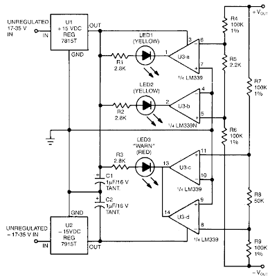
This schema uses two comparator pairs from an LM339N quad comparator; one pair drives the yellow positive (+)and negative (-)indicators, the other jointly drives the red warn LED3. The schema draws its power from the unregulated portion of the power supply. The four comparators get their switching inputs from two parallel resistor-divider strings. Both~strings have their ends tied between the power supply`s positive and negative output terminals. 

The first string, consisting of R4, R5, and R6, divides the input voltage in half, with output taps at 0.5%. The other string, made up of R7, R8, and R9, also divides the input voltage in half, with taps at + lO%. The 0.5% R4/R5/R6 string drives the two comparators controlling the positive and negative indicators (LEDl and LED2). Their inputs are crossed so that LED2 does not fire until the positive supply is at least 0.5% higher than the negative; the positive indicator does not go off until the negative supply is at least 0.5% higher than the positive-in relative levels. 

That overlap permits both LEDs to be on when the two supplies are in 1 % or better balance. The +lOT R7/R8/R9 string drives the other two comparators, which control the warn indicator. If either side of the supply is lO% or more higher than the other, one of the two comparators will switch its output low and light the redLED3the LM339N has opened-collector outputs, allowing such wired OR connections. The inputs are not crossed, as with the other comparator pair, so there is a band in the middle where neither comparators output is low and the LED remains off.

Power Supply Balance Indicator Circuit Diagram

Power Supply Balance Indicator Circuit Diagram

Read More..