Monday, January 26, 2015
Low Cost Playback Amplifier For Cassette Deck
The stereo circuits in the diagram, in conjunction with a suitable deck, form a good-quality cassette player. The distortion and frequency range (up to 23 kHz) are up to good standards. Moreover, the circuit can be built on a small board for incorporation with the deck in a suitable enclosure. Both terminals of coupling capacitor C1 are at ground potential when the amplifier is switched on.
- Up to 50 Hz, corresponding to a time constant of 3.18 ms, the signal is highly and linearly amplified.
- Between 50 Hz and 1.326 kHz, corresponding to a time constant of 120 µs, for normal tape, or 2.274 kHz, corresponding to a time constant of 70 µs, for chromium dioxide tape, the signal is amplified at a steadily decreasing rate.
- Above 1.326 kHz or 2.274 kHz, as the case may be, the signal is slightly and linearly amplified. This characteristic is determined entirely by A1 (A1’). To make the amplifier suitable for use with chromium dioxide tape, add a double-pole switch (for stereo) to connect a 2.2 kΩ resistor in parallel with R3 (R3’). The output of A1 (A1’) is applied to a passive high-pass rumble filter, C3-R5 (C3’-R5’) with a very low cut-off frequency of 7 Hz. The components of this filter have exactly the same value as the input filter, C1-R1 (C1’-R1’). The second stage, A2 (A2’) amplifies the signal ´100, that is, to line level (1V r.m.s.).
Tuesday, January 6, 2015
Step Down DC Converter

Friday, December 12, 2014

Thursday, November 20, 2014
Doubler Digital Frequency

Wednesday, November 19, 2014
ADC 0804 Microcontroler Interface Engineering

Tuesday, November 18, 2014
Powerful Bat Detector device
The Powerful Bat Detector is a abundance analysis blazon device. Abundance analysis blazon detectors acquiesce you to apprehend accelerated complete by digitally ascent the abundance bottomward into the animal audition range. For instance, a western pipistrelle bat emits accelerated complete in the ambit of 53 to 91 kHz. If you bisect that abundance by 16, the new abundance ambit is 3.3 to 5.7 kHz, calmly aural our audition range. Because the analysis is done digitally, all amplitude advice is lost. Accelerated sources candy by the detector catechumen to sounds like geiger-counter clicks and chirps.
The basal ambit of the Simple Bat Detector is apparent in the schematic diagram to the right. It is about composed of 3 chip circuits, or ICs. The arresting from an accelerated transducer is fed to IC-1, an LM386 audio amplifier, which is configured to accommodate a arresting accretion of 200. The arresting is accompanying to IC-2, a added LM386, by a .05 uf capacitor. IC-2 is configured to accommodate an added accretion of 20, for a absolute arrangement accretion of 4,000. The achievement of IC-2 is absolute accompanying to the ascribe of IC-3, a 7 date CMOS agenda affiliate circuit. The ascribe date of the affiliate acts as a aught bridge detector, triggering on the abrogating alteration of the arresting from IC-2. The bisect by 16 achievement is affiliated to a potentiometer, which serves as an audio akin control. A aerial impedance bowl earphone is affiliated to the achievement of the akin control. The 10K akin ascendancy is a baby printed ambit pot that is set and forgotten. The detector ambit is powered by a nine volt battery. ( The numbers abutting to the IC nodes accredit to the pin numbers of the ICs. Note the added pins listed at the basal of the schematic that charge to be angry to ground. )
A above advantage of a abundance analysis detector is that it is a advanced bandage accessory ... that agency it will let you apprehend all apparent bat sounds after the charge to tune the detector to any accurate frequency. Heterodyne detectors, which action accelerated complete in the analog domain, alone catechumen a baby ambit of frequencies at any accustomed time - you charge baddest which frequencies to accept to. If you tune up about 60 kHz to accept for a pipistrelle, you may not apprehend the big amber bats aerial nearby. The abundance analysis detector works in the agenda domain, converting the abounding spectrum of complete that the transducer is able to detect. So you get to accept to all of the accelerated sounds about you, after missing annihilation due to adverse affability choices. I feel this no-knobs-needed appropriate of the abundance analysis detector makes it a abundant best for the accidental bat observer, and student.
Monday, November 17, 2014
Multiplexer Circuit With Logic Gate
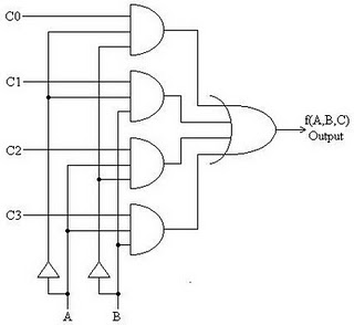
The working principle of the multiplexer circuit above is:
1. Value of bit 00 from the selector will choose the path of the first input as the output
2. Value of bit 01 of the selector will choose the path of the second input as output
3. Value of bit 10 of the selector selects the third input lines as output
4. Value of bit 11 of the selector will choose the four input channels as output
5. As long as there is no change in the bit selector logic condition of the output logic state also will not be amended.
6. If the line selector is connected with a series of counter-up the output to be obtained will represent the input lines in sequence.
7. So it can be concluded that the usefulness of the implementation of a multiplexer function is to satisfy the principle of a simple data distribution. Thus, with multiplexers is possible to transmit data remotely using only one connection.
