Showing posts with label power. Show all posts

Saturday, November 15, 2014

100W MOSFET POWER AMPLIFIER

A 100W MOSFET power amplifier circuit based on IRFP240 and IRFP9240 MOSFETs is shown here. The amplifier operates from a +45/-45 V DC dual supply and can deliver 100 watt rms into an 8 ohm speaker and 160 watt rms into a 4 ohm speaker. This Hi-Fi amplifier circuit is suitable for a lot applications like general purpose amplifier, guitar amplifier, keyboard amplifier. The amplifier can be also used as a sub woofer amplifier but a subwoofer filter stage has to be added before the input stage. The amplifier has a low distortion of 0.1%, a damping factor greater than 200, input sensitivity of 1.2V and the bandwidth is from 4Hz to 4 KHz.

Circuit Diagram


About the Circuit

Capacitor C8 is the input DC decoupling capacitor which blocks DC voltage if any from the input source. IF unblocked, this DC voltage will alter the bias setting s of the succeeding stages. Resistor R20 limits the input current to Q1 C7 bypasses any high frequency noise from the input. Transistor Q1 and Q2 forms the input differential pair and the constant current source circuit built around Q9 and Q10 sources 1mA. Preset R1 is used for adjusting the voltage at the output of the amplifier. Resistors R3 and R2 sets the gain of the amplifier. The second differential stage is formed by transistors Q3 and Q6 while transistors Q4 and Q5 forms a current mirror which makes the second differential pair to drain an identical current. This is done in order to improve linearity and gain. Power amplification stage based on Q7 and Q8 which operates in the class AB mode. Preset R8 can be used for adjusting the quiescent current of the amplifier. The network comprising of capacitor C3 and resistor R19 improves high frequency stability and prevents the chance of oscillation. F1 and F2 are safety fuses.

Circuit Setup

Set R1 at midpoint before powering up and then adjust it slowly in order to get a minimum voltage (less than 50mV0 at the output. Next step is setting up the quiescent current and keep the preset R8 in minimum resistance and connect a multimeter across points marked X & Y in the circuit diagram. Now adjust R8 so that the multimeter reads 16.5mV which corresponds to 50mA quiescent current.

Notes

  • Assemble the circuit on a good quality PCB.
  • Use a +45/-45 V DC, 3A dual supply for powering the circuit.
  • Power supply voltage must not exceed +55/-55 V DC.
  • Before connecting the speaker, check the zero signal output voltage of the amplifier and in any case it should not be higher than 50mV. If it is higher than 50mV, check the circuit for any error. Replacing Q1, Q2 with another set could also solve the problem.
  • Fit Q7 and Q8 to a 2°C/W heat sink. Both Q7 and Q8 must be isolated from the heat sink using mica sheets. Heat sink mounting kits for almost all power transistors/ MOSFETs of almost all package styles are readily available in the market.
  • All resistors other than R10, R11 and R19 are 1/4 watt metal film resistors. R10 and R11 are 5W wire wound type while R19 is a 3W wire wound type.


Power Supply for the 100W MOSFET Power Amplifier


Read More..

Thursday, November 13, 2014

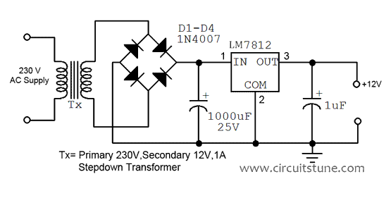
12V fixed voltage power supply circuit diagram

Here this circuit diagram is for +12V regulated (fixed voltage) DC power supply. These power supply circuit diagram is ideal for an average current requirement of  1Amp. This  circuit is based on IC LM7812. It is a 3-terminal (+ve) voltage regulator IC. It has short circuit  protection , thermal overload protection.  LM7812 IC is from LM78XX series. The LM78XX series IC is  positive voltage regulator IC for different voltage requirements, for example LM7805 IC is made for 5 volt fixed output voltage . There is LM79XX IC series for negative voltage .

Circuit diagram of 12V fixed voltage power supply


A transformer(Tx=Primary 230 Volt, Secondary 12 Volt , 1Amp step down transformer) is used to covert 230V to 12V from mains. Here used a bridge rectifier made by four  1N4007 or 1N4003 diode to convert AC to DC . The filtering capacitor 1000uF,25V is used to reduce the ripple and  get a smooth DC voltage. This circuit is very easy to build. For good performance input  voltage should be greater than 12Volt in pin-1 of IC LM7812. Use a heat sink to IC LM7812 for safeguarding it  from overheating.


12
Fig: 12V power supply circuit diagram
Read More..

Saturday, November 8, 2014

USB Power Booster

The USB serial bus can be configured for connecting several peripheral devices to a single PC. It is more complex than RS232, but faster and simpler for PC expansion.Since a PC can supply only a limited power to the external devices connected through its USB port, when too many devices are connected simultaneously, there is a possibility of power shortage. Therefore an external power source has to be added to power the external devices.
Circuit diagram:
USB Power Booster Circuit Diagram
In USB, two different types of connectors are used: type A and type  B. The circuit presented here is an add-on unit, designed to add more power to a USB supply line (type-A). When power signal from the PC (+5V) is received through socket A, LED1 glows, opto-diac IC1 conducts and TRIAC1 is triggered, resulting in availability of mains supply from the primary of transformer X1. Now transformer X1 delivers 12V at its secondary, which is rectified by a bridge rectifier comprising diodes D1 through D4 and filtered by capacitor C2.
 Pin configurations of moc3021, bt136 and 5v regulator 7805 
Regulator 7805 is used to stabilise the rectified DC. Capacitor C3 at the output of the regulator bypasses the ripples present in the rectified DC output. LED1 indicates the status of the USB power booster circuit. Assemble the circuit on a general-purpose PCB and enclose in a suitable cabinet. Bring out the +5V, ground and data points in the type-A socket. Connect the data cables as assigned in the circuit and the USB power booster is ready to function
Read More..

Friday, November 7, 2014

LM723 Variable Power Supply with Over Current Protection

The circuit design was intended to create an adjustable power supply over a range of 1.3V to 12.2V at 1A and be able to provide protection for over-current by utilizing LM723 regulator.


 Terminology
  • LM723 – a positive NPN standard voltage regulator mainly designed for series regulator applications which can be utilized for both foldback and linear current limiting due to its very low standby current drain circuit
  • Voltage Regulator – an electrical or electronic device created for the purpose of maintaining a constant voltage level of a power source within the suitable limits
  • 2N3055 – a complementary Silicon Epitaxial-Base planar NPN transistor mounted in Jedec TO-3 metal case for use as power transistor
Circuit Explanation
The integrated voltage regulator LM723 will supply 150 mA of output currents but any desired load current can be provided by adding external transistors for output currents in excess of 10A. This can be used as a linear or switching regulator since its output voltage can be adjusted from 2 Volts to 37 Volts while the input voltage can be at 40 Volts maximum. The range of variations of input voltage and load current can be kept at constant using this voltage regulator.

In this design, the DIL14 plastic packaged LM723 performs with 9.5V to 40V input DC voltage while having an output voltage that is not more then 6V to 7V below the input will lead to 150 mA current source from  the IC. The difference between the input and the output DC voltage plus the current is proportional to the amount power being dissipated by the transistor T1 as it accepts all the current brought by the load, thus requiring a heatsink with a heat conductive value of 5K/W. T1 is made from 2N3055 which is intended for series and shunt regulators, for output stages and high fidelity amplifiers, and for power switching circuits. The output stage of the integrated circuit will be less loaded when an external pass transistor is used which will conduct at emitter-follower mode. This will in turn cause T1 to conduct at base-emitter mode thereby producing a major resistance in the IC.

Both ceramic capacitors must be positioned closer to the integrated circuit to prevent undesired oscillations, which the LM723 is prone to, since ceramic capacitors have high frequency coefficient of dissipation. Having these capacitors directly soldered would be too much for the IC since the operating temperature of the IC is in the range of -55ᵒC to +125ᵒC

Application
Voltage regulators are used for several advantages in areas where uncontrolled voltage varies more than the accepted voltage of equipment which could be harmful and damaging. In motor vehicles, it matches the charging requirements of the battery and electrical load to the output voltage of the generator by rapidly switching from one to another of three circuit states using a dual pole switch loaded with spring. To keep a recommended range of voltage supplied to a consumer, regulators are used by alternating current distribution feeders or large scale power distributions or substations. This is useful in protecting the equipment using electricity by minimizing the variations in voltage.  The two types of regulators being used are step regulators where the current supply is controlled and the induction regulator where an induction motor adjust the voltage by supplying a secondary which smoothens the feeder line’s current variations.
The LM723 voltage regulators are widely used for wide range of applications such as a temperature controller, a current regulator, or a shunt regulator. Also, DC power supplies in electronic equipment are using voltage regulators.

Source:zen22142.zen.co.uk/Circuits/Power/723psu.htm
Read More..

Sunday, November 2, 2014

Low Power LED Flasher

It doesnt get much simpler than this circuit. Four components counting the battery!

How can an LED be illuminated by a 1.5V circuit, when the forward voltage of an LED is about 2V? The LM3909 uses the 100uF capacitor as a charge reservoir, building up a voltage of about 2V before discharging the cap through the LED.

This circuit is used in emergency flashlights on airplanes and in other public places. Though you may not have known it till now, the LM3909 is everywhere!

Low Power LED Flasher
Read More..

Sunday, October 5, 2014

5 to 15V 400mA Regulated Power Supply

5 to 15V 400mA Regulated Power Supply

This project is a simple DC regulated power supply that has a variable DC voltage range from 5V to 15V. It can supply current up to a 400mA to power the various circuits for your electronic projects. The voltage output is varied by using the potentiometer VR1. In this circuit, the input line power supply is designed for 240VAC. If 110VAC input is used, change the ratings of the varistor to 150VAC and the transformer ratio to 110V/12V.

Fuse F1 is used as a protection in case there is any short circuit in the circuit. Varistor V1 is connected in parallel to the input of the line voltage to clamp the surge voltage from the line to a reasonable level that helps to protect the transformer and other circuitry. Once the voltage level surge to a high level beyond the ability of the varistor to absorb it, fuse F1 or varistor V1 or both will burn. If this circuit failed after a period of operation, check that the fuse and the varistor are still in good condition or else replace them.

Diodes D1, D2, D3 and D4 are used to rectify the 12VAC voltage to DC voltage. Electrolytic capacitor E1 is used as a smoothing capacitor to reduce the ripple of the DC voltage. The DC voltage is fed into the input of 7805 regulator where the output DC voltage is obtained. Changing the value of VR1 will change the output of the DC voltage. Capacitor C1 is used to filter out high frequency component from the power supply.
Read More..

Wednesday, September 10, 2014

9 Volt DC Power Supply Using LM317 Regulator

There are many ways to obtain a very stable voltage 9VDC which has very minimal distortion. If you really love in the audio field, you must have a power supply at the level of the OP Amp should be free from hum. Use of Power Supply which has a higher stabilization and free of humming and buzzing frequently encountered in the use of communication tools such as Handy-talkie and radio transmitters.


Power
To overcome the above problem, we have to provide the filters on the power supply using IC regulator. You can use the LM 7809 or you can also use the regulator IC LM 317. This regulator has advantages over the use of IC 78XX. LM317 has a nature that is at the Gate (no.1 feet) can be tuned to provide feedback which is inversely proportional to the value of R (resistor). The R value can affect the output voltage on pin 2(V-out), pin 3 as input (V-in). The function R can be replaced with a variable resistor, but you must have an indicator meter or AVO meter to ensure that the output voltage is true 9 Volt. If youve found your desired voltage, for example 9VDC, then you can connect to the component that you want to turn on. So first set the output voltage using a volt meter before connecting to the equipment to be you turn on.
Power
KA317 / LM317 is a Three Terminal Positive Adjustable Regulator integrated schema, the monolithic characteristic adjustable positive voltage regulator designed to supply more than 1.5 A of load current with output voltage can be adjusted with a range capability 1.2 V of up to 37 V. This tool will work for internal current limiting, thermal shut-down and securing the compensation scope. You have to use aluminum as an additional cooling.

This schema will deliver 9V regulated DC voltage at maximum current of about 1A. The schema uses a transformer with a secondary output voltage 15-24V AC/1A. To give input in Primary of transformer, it’s dependent electrical conduit installation in your home. If the mains voltage 110V, then you have to find a 110V in transformer primary voltage. For the diode, you can use 4 pieces diodes 1N4002 (1A rectifier diode) or better by using a diode bridge 2A.
Power
9 Volt DC Power Supply Using LM317 Regulator
In the following schema scheme, we can see the typical basic application into obtaining voltage can be adjusted.
Read More..

Tuesday, September 9, 2014

Subwoofer amplifier with 30W output power

hifi
Amplifier circuit is very suitable for use in subwoofer amplifier system based on IC SI1030G. Amplfier has 30W output with 8 ohm impedance. Supply voltage required minimum of 12 volts and a maximum of up to 22 volts DC.

subwoofer
Component List :
R1 = 100K
R2 = 1R
C1 = 2.2uF
C2 = 100uF
C3 = 47uF
C4 = 100nF
C5 = 10uF
C6 = 47uF
C7 = 100uF
IC = SI1020GL , SI1030G
Read More..

Power amplifier 450W with sanken

Circuit of power amplifiers with power output of 450 watts mono , amplifiers are also frequently used in the amplifier a high-power amplifier, which used in an event, in the field and the placed closed. Because this amplifier suitable for the woofer, fullrange speaker, and can also be fixed for the subwoofer speaker. To further strengthen and maximize the amplifier ,its power supply circuit also must be accurate, for electrolytic capacitors in power supply ,voltage capacitors use 80V or more, and a capcity 20000uF upwards, so when the bass amplifier is high , the voltage is not lot of experience dropping. Diode bridge use a minimum of 35A, or adjust the current input voltage. If the power supply has fulfilled the desire, the supply to the power amplifier.
In the buffer circuit uses PNP transistor A1266 / A564 / A733 /A1015 / A798 and NPN with MJE340.To the driver circuit using PNP transistor MJE350 and MJE350. For the final amplifier circuit use two set 2SC2922 and 2SA1216. Use a quality sanken transistor to maximize quality sound output.

Below is the amplifier and finshed PCB layout.

bottom view

Top view
If the track pcb does not look, you can download this series in the form of fort board, use the eagle cadsoft application to open it, but its components are not ordered , to their own satisfaction you can design it with your whishes.
 Download file .brd here

Installation power amplifier

This is power supply

already amplifier
Read More..

Monday, September 8, 2014

LM2005 20 Watt Automotive Power Amplifier

General Description for LM2005:

The LM2005 is a dual high power amplifier, designed to deliver optimum performance and reliability for automotive deliver optimum performance and reliability for automotive vice to deliver 10W/channel into 2X (LM2005T-S), or 20W bridged monaural (LM2005T-M) into 4X, with low distortion. 

Features for LM2005:

Wide supply range (8V –18V)
Externally programmable gain
With or without bootstrap
Low distortion
Low noise
High peak current capability
POe20W bridge
High voltage protection
AC and DC output short circuit protection to ground or across load
Thermal protection
Inductive load protection
Accidental open ground protection
Immunity to 40V power supply transients
3§C/W device dissipation
Pin for pin compatible with TDA2005


Circuit diagram for LM2005:
LM2005 20 Watt Automotive Power Amplifier

Datasheet for LM2005: Download
Read More..

The pair of transistors power amplifier

Already Know about the transistor above? transistor above is one of the transistors that are applied at the amplifier end audio amplifiers. Because the power output and good quality of this transistor is very popular with high-power amplifier makers.
Transistors on no other than is 2SC2922 and 2SA1216, transistor pair is already very well known as a reliable amplifier. With a price not too expensive and not too large transistor large is also very suitable. And this transistor has its own code for its quality, its code is like 5DY, 57P, 85Y, 92P, etc.. to see datsheet transistor can be seen below.

Maximum Voltage  180V
maximum collector current  17A
Total power output  200W
To more clearly and accurately datasheet can be found here.
Read More..

Saturday, September 6, 2014

5 to 15V 400mA Regulated Power Supply

5 to 15V 400mA Regulated Power Supply

This project is a simple DC regulated power supply that has a variable DC voltage range from 5V to 15V. It can supply current up to a 400mA to power the various diagram for your electronic projects. The voltage output is varied by using the potentiometer VR1. In this schema, the input line power supply is designed for 240VAC. If 110VAC input is used, change the ratings of the varistor to 150VAC and the transformer ratio to 110V/12V.

Fuse F1 is used as a protection in case there is any short schema in the schema. Varistor V1 is connected in parallel to the input of the line voltage to clamp the surge voltage from the line to a reasonable level that helps to protect the transformer and other schemary. Once the voltage level surge to a high level beyond the ability of the varistor to absorb it, fuse F1 or varistor V1 or both will burn. If this schema failed after a period of operation, check that the fuse and the varistor are still in good condition or else replace them.

Diodes D1, D2, D3 and D4 are used to rectify the 12VAC voltage to DC voltage. Electrolytic capacitor E1 is used as a smoothing capacitor to reduce the ripple of the DC voltage. The DC voltage is fed into the input of 7805 regulator where the output DC voltage is obtained. Changing the value of VR1 will change the output of the DC voltage. Capacitor C1 is used to filter out high frequency component from the power supply.
Read More..

Friday, September 5, 2014

1 3 12V Small Variable Power Supply


This is a small variable power supply delivers adjustable output voltage of 1.3v-12v. The current output determined by R3. With current setting (see part list), it will deliver current output about 1A.


Detail Specification:
Output (approximate values):

Vmin = (R4 + R5) / (R5*1.3)
Vmax = (7.15 / R5) * (R4 + R5)
Imax = 0.65/R3
Max. Power on R3: 0.42/R3
Min. Input DC Voltage (pin 12 to pin 7): Vmax + 5

Parts List
B1 = 40V/2.5A
R1 = 1k ohm
R2 = Potensiometer 5k ohm
R3 = 0.56R/2W
R4 = 3.3k ohm
R5 = 4.7k ohm
C1 = 2200uF (3300uF even better)
C2 = 4.7uF
C3 = 100nF
C4 = 1nF
C5 = 330nF
C6 = 100uF
D1 = Green LED
D2 = 1N4003
F1 = 0.2A F
F2 = 2A M
IC1 = LM723 (in a DIL14 plastic package)
S1 = 250V/1A
T1 = 2N3055 on a heatsink 5K/W
TR1 = 220V/17V/1.5

R2 sets the output voltage. The maximum current is decided by the value of R3: the over-current protection schemary inside the LM723 senses the voltage across R3 and starts shutting the output stage off as soon as this voltage approaches 0.65 V. This way the current through R3 can never exceed 0.65/R3, even if the output is shorted.

C3 and C4, both ceramic, must be placed as close as possible to the integrated schema, because the LM723 can be prone to unwanted oscillations. It is not an overkill to solder them directly (and very carefully) to the pins of the IC. All other connections should also be kept short.

The LM723 works with input DC voltages from 9.5 to 40 V and the IC itself can source some 150 mA if the output voltage is not more than 6-7 V below the input. When an external pass transistor is used (in the usual emitter-follower mode), the base-emitter junction of T1 represents a significant resistance and the integrated diagram output stage is relatively lightly loaded. All the current drawn by the load passes through T1 and it dissipates an amount of power that is directly proportional to the current and the difference between the input and the output DC voltage.
Read More..

TDA7294 150 W Power Amplifier

This is power amplifier based on IC TDA7294 with output power 150W with 8 ohm impedance, source voltage + - 25V. for circuit see image below.

TDA7294
TDA7294 Power Amplifier
Read More..

Power amplifier circuit 60 W mono

Wow this is nice intregated amplifier circuit , because this IC can be power output up to 60 Watt . With minimum require voltage 8 V , and maximum voltage 35 V . But this circuit isnt so good to working on car , because output sound is very loud but not smooth. Amplifier so good working on full range , with speaker full range 100W and impedance 8 Ohm.
Below it is schematic :


Click to view large

The circuit above use IC AN7170 , the original output power IC is 20 W with impedance. But with use the circuit output elevated up to 60W.
Read More..

Thursday, September 4, 2014

LM1875 20 Watt Audio Power Amplifier

20
20 Watts Power Amplifier circuit can be made ​​with an IC power amplifier LM1875. IC LM1875 is a single chip power amplifier from National. 20 watts audio amplifier with LM1875 is a low power amplifier with good quality to the room.


To assemble the amplifier 20 watts with IC LM1875 component is not needed much support. 20 watts power amplifier using LM1875 IC in this article using symmetrical power supply. The series of 20 watts audio power amplifier with IC LM1875 can be used as an experiment or first project for the reader, because it is simple and assembly of high success.

LM1875
Schematic Amplifier LM1875

LM1875 amplifier circuit with the above may result in the strengthening of the voltage up to 27dB for each channel (1 channel 1 IC). Strengthening the voltage can be changed by changing the feedback that is R5 R (on the circuit above using R 22K). But the tension reinforcement can not be less than 20 dB because it can cause oscillation. For the power supply or power supply 20 watts power amplifier rngakaian with lm1875 can use travo 2-3A with CT.
Read More..

Build a 250 to 5000 watts PWM DC AC 220V Power Inverter

Build a 250 to 5000 watts PWM DC/AC 220V Power Inverter 

Build

Build

Build

Build

Build

Build

Build


This is my schematic design of a Pulse Width Modulator DC/AC inverter using the chip SG3524 .
I have built this design and using it as a backup to power up all my house when outages occur.

If you like my work and intend to build the schema dont forget to give me the 5 satrs :D and subscribe to me by clicking on the "follow" button so I know how many people benefit from the design, Thanks

Notes:

>The schematic schema design is for a 250 watt output, while the pics are of my 1500 watts inverter that i built, to increase the power of the schema you have to add more of the Q7 and Q8 transistors in parallel, each pair you add will increase your power by 250 watts, ex: to get 750 watts of power from the inverter you need to add in parallel 2 of Q7 and 2 of Q8 to the original design.

>If you increase the power transistors you have to enlarge the T2 transformer to match the new needs, the diagram transformer is rated 25 amps to handle 250 watts of 220v, for every 1 additional amp you need on the 220v side you have to increase 10 amps on the 12v side, of course there are limits to the thickness of the winding so if you need more than 750 watts i recommend that you use a 24VDC supply instead of 12 volts:

DC voltage and Transformer "T2" winding recommendation:
Power     Supply     Winding
750w       12VDC     P:24V "12-0-12" / S:220V
1500w     24VDC     P:48V "24-0-24" / S:220V
2250w     36VDC     P:72V "36-0-36" / S:220V
3000w     48VDC     P:96V "48-0-48" / S:220V
3750w     60VDC     P:120V "60-0-60" / S:220V
4500w     72VDC     P:144V "72-0-72" / S:220V
5250w     84VDC     P:168V "84-0-84" / S:220V
*The transformer should be "center tapped" at the primary side.
**You can make the secondary 110v if needed.
***The transformer in the pic is a custom made (48V center tapped / 220v ) 2000 watts, weights like 10 kilos.

>R1 is to set the PWM duty cycle to 220v. Connect voltmeter to the output of your inverter and vary VR1 till the voltage reads 220V.

>R2 is to set the frequency to 50 or 60 Hz (R2 range is between 40Hz to 75Hz), so guys that do not have a frequency meter are advised to blindly put this variable resistor mid-way which should drop you in the range of 50~60 Hz.
If you want you can substitue the variable resistor with a fixed resistor using the following formula: F = 1.3 / (RxC)
in our case to get a 50Hz output we remove both the 100K and the variable 100K both from pin 6 and we put instead a 260K fixed resistor and we leave the 0.1uF (the 104 cap) as it is, this change should give out a fixed 50Hz as per the formula :
1.3 / (260,000 ohm x 0.0000001 farad) = 50Hz
But in reality it will not exactly give 50Hz because the 260K resistor has a specific error value margin so does the capacitor, thats why i recommend a variable resistor so that accurate calibration can be achieved.

>Use either tantalum or polyester film "as in pic" for the 104 caps, ceramic disc caps change value once hot and this in turn changes the frequency of the inverter so they are not recommended.

>Pin 10 of the SG3524 can be used to auto shut down the inverter, once a positive voltage is given instead of negative to pin10, the SG3524 will stop oscillating. This is useful for persons wanting to add some cosmetic makeup to their inverters like overload cutoff, low battery cutoff or overheating cutoff.

>Wiring connections on the power stage side should be thick enough to handle the huge amps drain from the batteries. I marked them with dark black on the schema also I included a pic so you see how thick those wires must be.

>The design does not include a battery charger since each person will be building a custom version of the inverter with specific power needs. If you are ordering a custom made transformer you can ask them to take out for you an additional output wire on the primary side to give 14v (between point 0 and this new wire) and use it to charge a 12v battery, of course this needs a seperate schema to control charging auto cut-off. But anyway this is not advisable because it will shorten the life of the transformer itself since using it as a charger will toast the enamel coating layer of the copper wires over time. Anyway .. YES can be done to reduce cost.

>A cooling fan will be needed to reduce heat off the heat sinks and transformer, i recommend getting a 220v fan and connecting it to the output T2 transformer, when you power up the schema the fan will start this will always give you a simple way to know that 220v is present and everything is OK.. You can use a computers old power supply fan if you like.
Note that the fan must suck air out from the inverter case and NOT blow inside, so install it the correct way or it will be useless.
Also note how I fixed both the heat sinks and where the fan is, in a way that the fan sucks hot air from like a channel between the 2 heatsinks.

>2 schema breakers are recommended instead of fuses, one on the DC side and one on the AC side, depending on your design
Ex: for a 24vDC ( 1500 watts design ) put a 60Amp breaker on the DC side and a 6Amp on the AC side.
For every 1amp of 220vAC you will be draining like 8 to 10 Amps from the 12v battery, make your calculations !

> The 2 Heat sinks should be big enough to cool the transistors, they are separate and should NOT touch each other. "see the pics"

>Important: If youre building a big design that uses more than 24VDC as power source, make sure not to supply the driver schema with more than 24v maximum. (EX: If you have 4 batteries 4x12 = 48v , connect the v+ supply of the driver schema to the second batterys (+) terminal with a thin 1 mm wire which is more than enough. this supplies the driver schema with +24v while supplies the power transformer with +48v)

> "Optional" : Deep Cycle batteries are your best choice, consider them for best results .. read more

> Be cautious when building this schema it involves high voltage which is lethal, any part you touch when the schema is ON could give you a nasty painful jolt, specially the heat-sinks, never touch them when the schema is on to see if the transistors are hot !! I ate it several times :)

> The optional "Low voltage warning" is already embedded in the PCB layout, you can disregard it and not install its components if you do not needed. It does not affect the functionality of the main schema.

> The Motorola 2N6277 is a heavy duty power transistor, it is used in many US tanks for its reliability but unfortunately it is a very hard to find part, instead you can substitute each 2N6277 with 2 x 2N3773 or any equivalent.

> Ive included an optional "Battery level indicator" schema diagram that has 4 LEDs, you can see it installed on the front panel of my inverter pic, it is functioning great and shows precisely how much juice the batteries still have. I have included a small relay that is powered by the last LED to auto shutoff the inverter once last LED is off.

>Also included an optional "Overload schema", it is very easy to build and can be calibrated to the desired overload current threshold cutoff point through the potentiometer VR1.

R1 is rated 5watts for inverters upto 1000 watts. For bigger versions of the inverter like 1000 to 3000 watts inverters, replace R1 (1 ohm, 5watts) with (1 ohm, 17watts) which should handle loads upto 10 VA.
Make sure you install a proper relay to handle big current drains.

 If you like my work; you can show your regards by hitting Facebook like button, following us on Google+ or Twitter, stumbling our posts on stumble upon . Stay tuned for more tech updates.
Read More..

5W power amplifier with IC TDA1016

This circuit use IC TDA1016 , minimum require voltage for this circuit 3 volt and maximum require voltage 15 volt .Its mono 5 Watt power output with impedance 4 Ohm , Current required 14 mA. In order for this circuit work optimally , the voltage should be at least 9 volts and the speakers should be higher 4 Ohm or equivalent, and use the speaker woofer. See Amplifier circuit schematic below :

Read More..

Wednesday, September 3, 2014

Simple Dual Regulated Power Supply Wiring diagram Schematic

This is a Simple Dual Regulated Power Supply Circuit Diagram. A regulated power supply is an embedded schema; it converts unregulated AC into a constant DC. With the help of a rectifier it converts AC supply into DC. In this schema, the 7815 regulates the positive supply, and the 7915 regulates the negative supply. The transformer should have a primary rating of 240/220 volts for europe, or 120 volts for North America. The centre tapped secondary coil should be rated about 18 volts at 1 amp or higher, allowing for losses in the regulator. An application for this type of schema would be for a small regulated bench power supply. 


Simple Dual Regulated Power Supply Circuit Diagram

Simple

Read More..

Fixed Voltage Power Supply

The fixed voltage power supply is useful in applications where an adjustable output is not required. This supply is simple, but very flexable as the voltage it outputs is dependant only on the regulator and transformer you choose. The maximum output current is 1.5A. Fixed Voltage Power Supply Circuits diagram :   Parts : Part    Total     Description C1           1       2200uF 35V Electrolytic Capacitor C2, C4     2       0.1uF Ceramic Disc Capacitor C3           3       10uF 35V Electrolytic Capacitor

D1, D2    1        1N4007 Silicon Diode

BR1        1        2A 30V Bridge Rectifier

U1          1        Regulator (See Notes) T1          1        Transformer (See Notes) S1          1        SPST 2 Amp Switch F1          1        2A 250V Fuse and Holder  Misc      1        Heatsink For U1, Line Cord, Case, Wire  

Notes :

  1. Since this project operates from 120 (or 220, or 240, etc.) volts AC, it MUST be built inside a case.
  2. U1 will reauire a heatsink.
  3. You will need to choose T1 and U1 to match the voltage you want. Use the table below as a reference.

Read More..