Showing posts with label circuit. Show all posts

Friday, December 12, 2014

Electronic liquid detector circuit diagram


This electronic liquid detector circuit diagram is based on the ULN2429A monolithic bipolar integrated circuit designed for detecting the absence or presence of many different types of liquids. The ULN2429 electronic liquid detector circuit can be used in automotive , home or industrial applications . 
Read More..

Monday, November 17, 2014

Multiplexer Circuit With Logic Gate

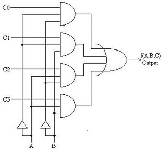
Multiplexer circuit with a logic gate is a multiplexer circuit that utilizes a combination of logic gates.
Where the above example can be seen that the circuit has 2 bit selector and 4 input lines. You can make a circuit with more input channels by increasing the number of bits of the selector. And also you can use a combination of gates based on your own design with reference to the previous multiplexer truth table you should specify. So by making a truth table in advance you can easily create a series of logic gates.


Multiplexer

The working principle of the multiplexer circuit above is:

1. Value of bit 00 from the selector will choose the path of the first input as the output
2. Value of bit 01 of the selector will choose the path of the second input as output
3. Value of bit 10 of the selector selects the third input lines as output
4. Value of bit 11 of the selector will choose the four input channels as output
5. As long as there is no change in the bit selector logic condition of the output logic state also will not be amended.
6. If the line selector is connected with a series of counter-up the output to be obtained will represent the input lines in sequence.
7. So it can be concluded that the usefulness of the implementation of a multiplexer function is to satisfy the principle of a simple data distribution. Thus, with multiplexers is possible to transmit data remotely using only one connection.
Read More..

Thursday, November 13, 2014

12V fixed voltage power supply circuit diagram

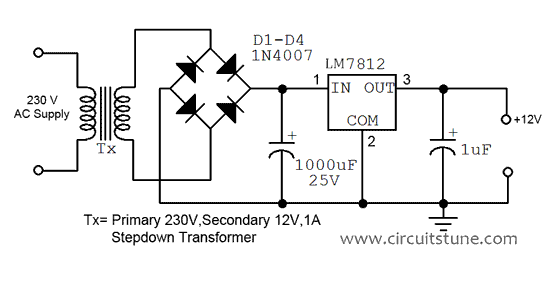
Here this circuit diagram is for +12V regulated (fixed voltage) DC power supply. These power supply circuit diagram is ideal for an average current requirement of  1Amp. This  circuit is based on IC LM7812. It is a 3-terminal (+ve) voltage regulator IC. It has short circuit  protection , thermal overload protection.  LM7812 IC is from LM78XX series. The LM78XX series IC is  positive voltage regulator IC for different voltage requirements, for example LM7805 IC is made for 5 volt fixed output voltage . There is LM79XX IC series for negative voltage .

Circuit diagram of 12V fixed voltage power supply


A transformer(Tx=Primary 230 Volt, Secondary 12 Volt , 1Amp step down transformer) is used to covert 230V to 12V from mains. Here used a bridge rectifier made by four  1N4007 or 1N4003 diode to convert AC to DC . The filtering capacitor 1000uF,25V is used to reduce the ripple and  get a smooth DC voltage. This circuit is very easy to build. For good performance input  voltage should be greater than 12Volt in pin-1 of IC LM7812. Use a heat sink to IC LM7812 for safeguarding it  from overheating.


12
Fig: 12V power supply circuit diagram
Read More..

Wednesday, November 12, 2014

ic NE 555 Timer IC Datasheet Applications and Circuit Schematics


NE-555 timer IC was being introduced around May 1971 by the Signetics Corporation, to become known as the NE-555 / SE-555, and was also the very first very mass-produced commercially produced timer IC available at that time. Philips semiconductor was then introduced this 555 timer in mid 1972. Its characteristics for versatility, stability, low cost, simplicity to produce long time delays in a variety of applications, make Electronic Engineers, Circuit Designers from mechanical timers, op amps, and various discrete circuits into the ever increasing ranks of timer users.

Invented by a clever Swiss man, Hans R. Camenzind in 1970, the NE-555 timer IC went on to become a legend in the industry. As we already know, the 555 timer operates in three basic mode: monostable (one shot), astable (oscilatory), and time delay. In the article below each of basic operating mode were described detailly in one sequence with its schematic diagrams.

Another sections you can follow in this datasheet applications are general design consideration of the 555 timer, frequently asked applications question (FAQ), design formulas, and sample of some ingenious applications. The sample of applications were presented such as Missing Pulse Detector, Pulse Width Modulation (PWM), Tone Burst Generator, Long Time Delays, Car Tachometer (click to enlarge the picture above), Auto Burglar Alarm, Cable Tester, Automobile Voltage Regulator, and more. Each sample is given with clear and detail circuit schematic diagrams.

The article is ended with Theory of Operation and The Speed Warning Circuit section. Read on complete information about The NE 555 Timer IC Datasheet Applications and Circuit Schematics with link to download in pdf document provided (source: doctronics.co.uk).

Read More..

Thursday, November 6, 2014

Off Line Telephone Tester Circuit Diagram

Here is a circuit of an off-line telephone tester which does not require any telephone line for testing a telephone instrument. The circuit is so simple that it can be easily assembled even by a novice having very little knowledge of electronics. A telephone line may be considered to be a source of some 50 volts DC with a source impedance of about 1 kilo-ohm. During ringing, in place of DC, an AC voltage of 70 to 80 volts (at 17 to 25 Hz) is present across the telephone line. When the subscriber lifts the handset, the same is sensed by the telephone exchange and the ringing AC voltage is disconnected and DC is reconnected to the Off Line Telephone Tester Circuit Diagram line. Lifting of the handset from the telephone cradle results in shunting of the line’s two wires by low impedance of the telephone instrument. As a result, 50V DC level drops to about 12 volts across the telephone instrument.

During conversation, the audio gets superimposed on this DC voltage. Since any DC supply can be used for testing a telephone instrument, the same is derived here from AC mains using step-down transformer X1. Middle point of the transformer’s secondary has been used as common for the two full-wave rectifiers—one comprising diodes D1 and D2 together with smoothing capacitor C1 and the other formed by diodes D3 and D4 along with filter capacitor C2. The former supplies about 12 volts for the telephone instrument through primary of transformer X2 which thus simulates a source impedance, and a choke which blocks AC audio signals present in the secondary of transformer X2. The AF signal available in secondary of X2 is sufficiently strong to directly drive a 32-ohm headset which is connected to the circuit through headphone socket SK1 via rotary switch S2. During ringing, a pulsating DC voltage from transformer X1 via rectifier diode D5, push-to-on switch S3, and contact ‘B’ of rotary switch S2 is applied across secondary of transformer X2.

The boosted voltage available across primary of transformer X2 is sufficient to drive the ringer in the telephone instrument. Please avoid pressing of switch S3 for more than a few seconds at a time to prevent damage to the circuit due to high voltage across primary of transformer X2. The circuit also incorporates a music IC (UM66) whose output is connected to secondary of transformer X2 via switch S2 after suitably boosting its output with the help of darlington transistor pair T1 and T2. This output can be used to test the audio section of any telephone instrument. After having assembled the circuit satisfactorily, the following procedure may be followed for testing a telephone instrument: 1. Connect the telephone to the terminals marked ‘To Telephone Under Test’and switch on mains (switch S1). 2. To test the ringer portion, flip switch S2 to position ‘B’ and press S3 for a moment. You should hear the ring in case the ringer circuit of the telephone under test is working. Please ensure that handset is on cradle during this test. 3. For testing the audio section, flip switch S1 to position ‘C’ and connect a headphone to socket SK1.

Pick the telephone handset and speak into its microphone. If audio section is working satisfactorily, you should be able to hear your speach via the headphone. If you dial a number, you should be able to hear the pulse clicks or pulse tone in the headphone, depending on whether the telephone under test is functioning in pulse or tone mode. If the telephone under test has a built-in musical hold facility, on pressing the ‘hold’ button you should be able to hear the music. Now flip switch S2 to position ‘A’. You should be able to hear music generated by IC1 through earpiece of the handset of the telephone under test, indicating propor functioning of the AF amplifier section. The circuit can be assembled on a small piece of veroboard. Try to mount the two transformers on opposite sides of the board, displaced by 90 degrees. Always keep handy multi-type modular plugs for testing various types of telephones. Mount all switches, sockets and LEDs on the front of testing panel
Read More..

Monday, November 3, 2014

Simple FM Telephone Bug Circuit

Here is a simple transmitter that when connected to a phone line, will transmit anything on that line (execpt the dial tone) to any FM radio. The frequency can be tuned from 88 to about 94Mhz and the range is about 200 feet. It is extremely easy to build and is therefore a good, useful beginner project.

FM Telephone Bug Circuit Diagram:

Telephone

Parts:
R1 180 Ohm 1/4 W Resistor
R2 12K 1/4 W Resistor
C1 330pF Capacitor
C2 12pF Capacitor
C3 471pF Capacitor
C4 22pF Capacitor
Q1 2SA933 Transistor
D1, D2, D3, D4 1SS119 Silicon Diode
D5 Red LED
S1 SPDT Switch
L1 Tuning Coil
MISC Wire, Circuit Board

Notes :
 
1. L1 is 7 turns of 22 AWG wire wound on a 9/64 drill bit. You may need to experiment with the number of turns.
2. By stretching and compressing the coils of L1, you can change the frequency of the transmitter. The min frequency is about 88 Mhz, while the max frequency is around 94 Mhz.
3. The green wire from the phone line goes to IN1. The red wire from the phone line goes to IN2. The green wire from OUT1 goes to the phone(s), as well as the red wire from OUT2.
4. The antenna is a piece of thin (22 AWG) wire about 5 inches long.
5. All capacitors are rated for 250V or greater.
6. The transmitter is powered by the phone line and is on only when the phone is in use. S1 can be used to turn the transmitter off if it is not needed.
7. If you have problems with the LED burning out, then add a 300 ohm 1/4W resistor in series with it.


Read More..

Thursday, October 30, 2014

Speech Filter Circuit Diagram

In communications receivers and microphone amplifiers for transmitting equipment, there is frequently a need for a narrow, low-frequency band-pass filter that lets only the voice band through. This band is usually defined to be the portion of the audio frequency spectrum between approximately 300 Hz and 3300 Hz. In order to implement such a filter, we have calculated the values for two fifth-order Butterworth filters having these corner frequencies and connected them in series. The result is a band-pass filter for the desired pass-band with a skirt steepness of 100 dB/decade.  The first opamp (IC1) acts as a buffer.

Speech Filter Image :

 
image


The circuit can be powered by a unipolar supply voltage between 5 V and 18 V, which is a broad enough range that it should always be possible to find a suitable voltage when building the filter into existing equipment. The current consumption of the filter is only a few milliampères, which should rarely pose a problem. There is fairly wide selection of suitable candidates for the opamps, since the circuit is not critical in this regard. In addition to the indicated OP27A, you could consider using a TL081N or even an old-fashioned 741.

Speech Filter Circuit diagram : 
Speech-Filter-Circut-Diagram
Speech Filter Circuit Diagram 


Due to unavoidable spreads in component values, the pass-band curve of the filter will never be completely perfect in actual practice. However, the deviations will be very small and in any case inaudible. In the pass-band region, the gain is approximately unity. The printed circuit board design shown here allows the speech filter to be built in a very compact form, which can be an important factor if it must be fitted into existing equipment. You can quickly check the fully assembled circuit by momentarily measuring the voltages at the inputs and out-puts of the three opamps. Half of the supply voltage should be present at all of these locations.

PCB Layout :


Parts LIST:
Resistors:
R1.R2 = 22kΩ
R3,R11,R12,R18,R19 = 100kΩ
R4 = 470Ω
R5 = 150Ω
R6 = 10kΩ
R7 = 18kΩ
R8 = 15kΩ
R9 = 33kΩ
R10 = 82kΩ
R13-R17 = 3kΩ3
Capacitors:
C1,C8,C14,C15 = 100nF
C2 = 1µF MKT
C3-C7,C11 = 22nF
C9 = 33nF
C10 = 18nF
C12 = 10nF
C13 = 4nF7
C16,C17 = 10µF 16V
Semiconductors:
IC1,IC2,IC3 = OP27A, TL081CN
Miscellaneous:
Bt1 = 9-V battery


Author: G.Baars
Read More..

Tuesday, October 28, 2014

Cell Phone Detector circuit diagram

The circuit can detect both the incoming and outgoing calls, SMS and video transmission even if the mobile phone is kept in the silent mode. The moment the bug detects RF transmission signal from an activated mobile phone, it starts sounding a beep alarm and the LED blinks. The alarm continues until the signal transmission ceases.
An ordinary RF detector using tuned LC circuits is not suitable for detecting signals in the GHz frequency band used in mobile phones. The transmission frequency of mobile phones ranges from 0.9 to 3 GHz with a wavelength of 3.3 to 10 cm. So a circuit detecting gigahertz signals is required for a mobile bug.

Here the circuit uses a 0.22μF disk capacitor (C3) to capture the RF signals from the mobile phone. The lead length of the capacitor is fixed as 18 mm with a spacing of 8 mm between the leads to get the desired frequency. The disk capacitor along with the leads acts as a small gigahertz loop antenna to collect the RF signals from the mobile phone.
Read More..

Thursday, October 16, 2014

Build a Period To Voltage Converter Circuit Diagram

The input signal drives ICD. Because ICD`s positive input (V+) is slightly offset to + 0.1 V, its steady stateoutput will be around +13 V. This voltage is sent to ICC through D2, setting ICC`s output to +13 V. Therefore, point D is cut off by Dl, and CI is charged by the current source. Assuming the initial voltage on CI is zero, the maximum voltage (^Cinax) is given by: 

When the input goes from low to high, a narrow positive pulse is generated at point A. This pulse becomes -13 V at point B, which cuts off D2. ICC`s V+ voltage becomes zero. The charge on CI will be absorbed by ICC on in a short time. 

The time constant of C2 and R5 determines the discharge period— about 10 /is. ICB is a buffer whose gain is equal to (R& + R9)~Rg = lM5. ICD`s average voltage will be (1362f 1.545) + 2 = 1052/. RIO and C3 smooth the sawtooth waveform to a dc output.


Period-To-Voltage Converter Circuit Diagram

Read More..

Monday, October 13, 2014

LM35 Digital Remote Thermometer circuit and explanation

Digital Remote Thermometer circuit with very high accuracy temperature measurement features are set using the IC package numbers
Receiver Module Functional
LM35 (Linear temperature sensor IC) through a power amplifier and voltage change as a form of high frequency. To signal through the AC power cord.
For the receiver circuit and display module will receive the high frequency AC power cord and decode out to be the actual temperature figures with digital IC No. CD4553 Three-digit BCD Counter IC) and IC-CD4511 (BCD-to-7-Segment Latch / Decoder / Driver IC).
 Electronic Part List
Receiver Module
R1   100K 1/4W
C1,C2  47nF 400V
R2  1K 1/4W
C3,C7  1nF 63V
R3,R4,R6-R8  12K 1/4W
C4  10nF 63V
R5  47K 1/4W
C5,C6,C10  220nF 63V
R9-R15  470R 1/4W
C8  1000uF 25V
R16  680 1/4W
C9  100pF 63V
D1,D2,D5  1N4148
D3,D4  1N4002
D6-D8  Common-cathode 7-segment LED mini-displays
IC1  403
IC2   4518
IC3  78L12
IC4  4017
IC5  4553
IC6  4511
Q1 BC239C
Q2-Q4  BC327

L1  Primary (Connected to C1 & C2): 10 turns
Secondary: 100 turns
Wire diameter: 0.02mm. enameled
Plastic former with ferrite core. Outer diameter: 4mm.

T1 220V Primary, 12+12V Secondary 3VA Mains transforme
Remote Module Functional
    The frequency pulses from the wall and safely isolated by C1, C2 and L1 are amplified by Q1, diodes D1 and D2 of the peak limit his admission. The pulses are filtered by C5, IC1b square, divided by 10 in IC2B and sent for final countdown clock input of IC5. IC4 is the time base generator: it provides IC1b and reset pulses to the making and IC5 locks and opening time of IC5 at 1Hz frequency. It is powered by a 5Hz square wave obtained from the frequency 50Hz sector Retrieved from T1 secondary, squared and divided by 10 in IC1C IC2A. IC5 readers across the cathodes scenes Q2, Q3 and Q4 with a rate determined by frequency multiplexing C7. Readers also shows three anodes in parallel by the BCD to 7 segments decoder IC6. In summary, the input pulse power on, say, 2kHz frequency be divided by 10 and displayed as 20.0 ° C


Remote Circuit
Electronic Part List


Remote Module
R1,R3  100K 1/4W
C1  220nF 63V
R2  47R 1/4W
C2  10nF 63V
R4  5K 1/2W Trimmer Cermet
C3  1uF 63V
R5  12K 1/4W
C4,C6  1nF 63V
R6  10K 1/4W
C5  2n2 63V
R7  6K8 1/4W
C7,C8  47nF 400V
R8,R9  1K 1/4W
C9  1000uF 25V
D1  1N4148
IC1  LM35
D2,D3  1N4002
IC2  LM331
D4   Red LED
IC3  78L06
Q1  BC238
Q2 BD139

L1   Primary (Connected to Q2 Collector): 100 turns
Secondary: 10 turns
Wire diameter: 0.02mm. enameled
Plastic former with ferrite core. Outer diameter: 4mm.

T1   220V Primary, 12+12V Secondary 3VA Mains transformer
Read More..

Thursday, October 2, 2014

Temperature Data Logger 4 Channel Four Channel

Heres a temperature data logger circuit, an 8-pin microcontroller based circuit for temperature data logging via the serial port of any computer from between 1 and 4 remote digital temperature sensors, DS1820/DS18S20 made by Dallas.

Features of the Temperature Data Logger are are follow:
  • Provides realtime data via the serial port.
  • Interfaces up to 4 x DS1820 sensors.
  • Accuracy to 0.5 degrees centigrade
  • Fahrenheit scale selected by a jumper
  • No external power required
  • Data stream easily logged & processed.
  • Over 200m distance for each sensor


The sensors of temperature data logger may be located more than 200 yards from the PCB. Just check that the remote VDD is above 4.4Volts. Its recommends 10uF tantalum capacitors be placed across the power supply pins (not supplied) to minimise random errors and possibly get increased range.


Download :
- Circuit Schematic and Parts List
- Sensor Specs DS1820 DS18S20
- Software for Windows and DOS
- Source Code
- Terminal Emulator 
Read More..

Wednesday, October 1, 2014

Stereo Cassette Player Circuit Diagram

As the equipment is mains operated, the battery compartment can be removed. The loudspeaker can also be removed as it is no longer required; the mains transformer may be fitted in its position. lf so desired, you · may add a neon indicator and a mains switch as well. Assembly cost and time As to the cost, you are lucky if you are in Delhi and can shop around Lajpatrai Market. The cost would be around Rs 400 or even less if you know the way the Delhi market works. Outside Delhi, the cost would be around Rs 450 much less than you would pay for a mono cassette recorder. lt is certainly worth every rupee that you spend as it would enable you to use the stereo system that you already own. Assembly time would depend on your familiarity with the electronic circuitry, but it would be a weekend well spent. (Time you need for shopping for the mechanism and parts would be extra.)  Two direct·coupled transistors are used in the preamplifier, with base bias for the first provided from the emitter of the second. This system of biasing results in heavy DC ° feedback that ensures stable operation of the circuit.


With the DC operating conditions stabilised, as mentioned, the AC characteristics of the preamplifier are also stabilised. The AC feedback from the collector of the second A transistor to the emitter of the first mainly provides frequency equalisation high frequency de-emphasis to compensate for the recording characteristics. To keep up a high signal- to-noise ratio in the high frequency range, the highs are boosted during recording. (This is called pre-emphasis.) A reverse treatment is therefore essential in playback to reproduce the original high-frequency signal correctly. An R- C combination, 22k with 5nF capacitor, carries out this function adequately.

Output from the preamplifier is fed to a 741 op-amp set for a gain of about ten. The total gain is thus around 1000 so as to provide a 100mV signal from 100uV input normally expected from a cassette head. Use of discrete preamplifier at the input ensures a good signal-to-noise ratio, and the op-amp at the output with a wide dynamic range ensures that there is no chance of signal being driven into saturation. The signal from the preamp is fed to inverting terminal number 2 of the op-amp through 5.6k resistor. Negative feedback from the output terminal number 6 through 68k is also provided to terminal number 2. The non-inverting terminal number 3 is set to half the supply voltage. That sets the DC voltage at terminal number 6. Thus an optimum swing of the output is possible at terminal number6. Positive supply terminal number 7 is taken to the supply positive, and terminal number 4 returned to ground. The output from the op-amp is taken out through a47k resistor to the standard 3.5 mm socket used in cassette recorders. The socket fits in a window provided in a ‘Sony’ cabinet for mono cassette recorder. `  
Read More..

Friday, September 19, 2014

Simple and hold circuit using op amp Circuits Wiring diagram

As the name indicates , a sample and hold schema is a schema which samples an input signal and holds onto its last sampled value until the input is sampled again. Sample and hold diagram are commonly used in analogue to digital converts, communication diagram, PWM diagram etc. The schema shown below is of a sample and hold schema based on uA 741 opamp , n-channel E MOSFET BS170 and few passive components.

Description

As the name indicates , a sample and hold schema is a schema which samples an input signal and holds onto its last sampled value until the input is sampled again. Sample and hold diagram are commonly used in analogue to digital converts, communication diagram, PWM diagram etc. The schema shown below is of a sample and hold schema based on uA 741 opamp , n-channel E MOSFET BS170 and few passive components.

In the schema MOSFET BS170 (Q1) works as a switch while opamp uA741 is wired as a voltage follower. The signal to be sampled (Vin) is applied to the drain of MOSFET while the sample and hold control voltage (Vs) is applied to the source of the MOSFET. The source pin of the MOSFET is connected to the non inverting input of the opamp through the resistor R3. C1 which is a polyester capacitor serves as the charge storing device. Resistor R2 serves as the load resistor while preset R1 is used for adjusting the offset voltage.
During the positive half cycle of the Vs, the MOSFET is ON which acts like a closed switch and the capacitor C1 is charged by the Vin and the same voltage (Vin) appears at the output of the opamp. When Vs is zero MOSFET is switched off and the only discharge path for C1 is through the inverting input of the opamp. Since the input impedance of the opamp is too high the voltage Vin is retained and it appears at the output of the opamp.

The time periods of the Vs during which the voltage across the capacitor (Vc) is equal to Vin are called sample periods (Ts) and the time periods of Vs during which the voltage across the capacitor C1 (Vc) is held constant are called hold periods (Th). Taking a close look at the input and output wave forms of the schema will make it easier to understand the working of the schema.

Circuit diagram

 Sample and Hold schema using uA741 opamp

Input and output waveforms.

sample
Input and output waveforms - Sample and hold schema

Notes

  • The schema can be assembled on a vero board.
  • Use +15V/-15V DC dual supply for powering the opamp.
  • Capacitor C1 must have minimum leakage current possible and thats why a polyester capacitor is used here.
  • Mount the IC uA741 on a holder.
  • The type number of the MOSFET Q1 is not very significant here and so substitution is possible if BS170 is not available.
  • BS170 is a 60V, 500mA n-channel enhancement mode MOSFET available in TO-92 package.
  • Preset resistor R1 can be used for offset adjustments.
Read More..

Wednesday, September 17, 2014

How to Build a FM Transmitter Circuit Diagram


How to Build a FM Transmitter Circuit Diagram. Lets start this simple FM Transmitter Circuit Diagram making. FM transmitter circuit schematic with a single transistor. It build with a very few numbers of components include a transistor, few capacitors, resistors and a small microphone. 
 
Read More..

Monday, September 15, 2014

Ultrasonic Wave Receiver Circuit

Ultrasonic Wave Receiver
Ultrasonic recipients will receive an ultrasonic signal emitted by an ultrasonic transmitter in accordance with the characteristic frequency. Received signal is going through the process of filtering using the frequency band pass filter circuit, with a frequency value that is passed has been determined. 
Read More..

Saturday, September 13, 2014

Sound Activated Lamp Relay Switch Circuit

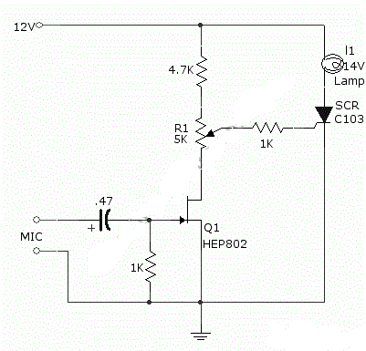
This simple Sound-Activated Lamp schema shown int the schematic diagram actives the switch using sound. We can use this schema for various applications, such as automatic (sound-controlled) disco light or car’s LED light show.  The Q1 amplify the audio from mic. The R1 is used to adjust the peak of signal to greater than about 0.7 volts, act as sensitivity adjuster. A certain level, the signal coming from microphone, after amplification by Q1, will trigger the SCR and light lamp I1. If we change the lamp with a relay, then we can get a sound-activated relay/switch, which can be used to control more powerful / high wattage high voltage lamps. If we use a relay, place a 1N4007 diode in parallel with the relay coil to prevent the back-emf from  relay coil destroying the SCR.

 Sound-Activated Lamp Circuit Diagram

 sound-activated lamp circuit diagram

Read More..

Friday, September 12, 2014

12V Latch Wiring diagram Schematic

This schema controls a solenoid by the operation of a single push-button switch. The schema will supply loads of over 1 A and can be operated up to a maximum speed of once every 0.6 second. When power is first applied to the schema, the solenoid will always start in its off position. Other features of the schema are its automatic turn-off, if the load is shorted, and its virtually zero-power consumption when off.

12V Latch Circuit Diagram

12V

Read More..

Wednesday, September 10, 2014

Simple Comperator Frequency LED Wiring diagram Schematic

This Simple Comparator Frequency LED Circuit Diagram uses a comparison frequency IC 74HCT00, the device enabling frequency pulses are compared. Frequency F1 (signal frequency channel 1) and F2 (signal frequency channel 2). If the two frequencies are equal, then LED lights.


Comperator Frequency LED Circuit Diagram

Simple


Read More..

Active band reject filter Circuit

A filter with a band-reject characteristic is frequently referred to as a notch filter. A typical schema using a µ 741 is the unity-gain configuration for this type of active filter shown. The filter response curve shown is a second-order band-reject filter with a notch frequency of 3 kHz. The resulting Q of this filter is about 23, with a notch depth of - 31 dB.Although three passive networks are used in this application, the operational amplifier has become a sharply tuned low-frequency filter without the use of inductors or large-value capacitors.

 Active band-reject filter Circuit Diagram

 active band-reject filter circuit diagran

Read More..

Tuesday, September 9, 2014

Buffer Circuit

The series is a series of input buffer equal to the output. In this is such a common collector circuit of air-reinforcement = 1. R value attached to restrict the current use is issued. Great value depends on the indication of its components, is usually not installed or flow is maximized in accordance with the op-amp capability.


Buffer circuit here serves to reinforce the clock signal and synchronization for robust enough to be transmitted through a cable with a considerable distance. buffer circuit should have a fairly low output impedance. because the synchronization clock line and this is the track "bus" that is connected to a series of client (branch) in parallel. output current should also be quite large, so as to move a few branches. output buffer in addition to pulse and synchronization signals can also be used as a source of supply.

Buffer circuit using Darlington pairs that have the advantage as expected above. strengthening the buffer is quite high. R base serves as aretaining basis.Vin flow is the input voltage that comes from a series of MMV ( multivibrator). Where active at the level of ± 6V Vin = VCC.
Read More..