Showing posts with label fixed. Show all posts
Showing posts with label fixed. Show all posts
Thursday, November 13, 2014
12V fixed voltage power supply circuit diagram
Here this circuit diagram is for +12V regulated (fixed voltage) DC power supply. These power supply circuit diagram is ideal for an average current requirement of 1Amp. This circuit is based on IC LM7812. It is a 3-terminal (+ve) voltage regulator IC. It has short circuit protection , thermal overload protection. LM7812 IC is from LM78XX series. The LM78XX series IC is positive voltage regulator IC for different voltage requirements, for example LM7805 IC is made for 5 volt fixed output voltage . There is LM79XX IC series for negative voltage .
Circuit diagram of 12V fixed voltage power supply
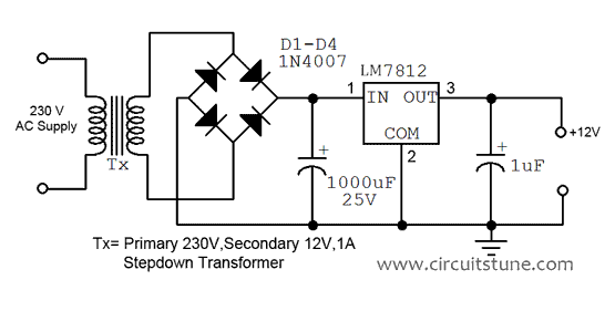 |
| Fig: 12V power supply circuit diagram |

Wednesday, September 3, 2014
Fixed Voltage Power Supply
The fixed voltage power supply is useful in applications where an adjustable output is not required. This supply is simple, but very flexable as the voltage it outputs is dependant only on the regulator and transformer you choose. The maximum output current is 1.5A. Fixed Voltage Power Supply Circuits diagram : ![]() Parts : Part Total Description C1 1 2200uF 35V Electrolytic Capacitor C2, C4 2 0.1uF Ceramic Disc Capacitor C3 3 10uF 35V Electrolytic Capacitor
Read More..
D1, D2 1 1N4007 Silicon Diode
BR1 1 2A 30V Bridge Rectifier
U1 1 Regulator (See Notes) T1 1 Transformer (See Notes) S1 1 SPST 2 Amp Switch F1 1 2A 250V Fuse and Holder Misc 1 Heatsink For U1, Line Cord, Case, WireNotes :
- Since this project operates from 120 (or 220, or 240, etc.) volts AC, it MUST be built inside a case.
- U1 will reauire a heatsink.
- You will need to choose T1 and U1 to match the voltage you want. Use the table below as a reference.
Subscribe to:
Posts (Atom)
