Showing posts with label audio. Show all posts
Showing posts with label audio. Show all posts
Sunday, September 7, 2014
20W Bridge Audio Amplifier based on TDA2005
This is 20W Bridge Audio Amplifier schema based on the TDA2005 IC, a class B dual audio amplifier, specifically designed for car radio applications etc.
This schema require Voltage input 18 VDC and will give you Output power - 20 W, 4 Ω
This is the amplifier kit:

This is the schematic:

To get the schematic diagram, component list and component layout, please download this file
Read More..
This schema require Voltage input 18 VDC and will give you Output power - 20 W, 4 Ω
This is the amplifier kit:
This is the schematic:
To get the schematic diagram, component list and component layout, please download this file

Saturday, September 6, 2014
TDA1009 Audio Amplifier 2 x 6 W
Description:
Vcc MIN (V)..........9 V
Vcc NOM (V)........14 V
Vcc MAX (V)........24 V
Pout (W)............2 x 6 W
R (Ohm).............4 Ohm
Tip case..............16-DIP+C
Circuit Diagram:
Vcc NOM (V)........14 V
Vcc MAX (V)........24 V
Pout (W)............2 x 6 W
R (Ohm).............4 Ohm
Tip case..............16-DIP+C
Circuit Diagram:
 |
| TDA1009 Circuit Diagram |
Thursday, September 4, 2014
LM1875 20 Watt Audio Power Amplifier
To assemble the amplifier 20 watts with IC LM1875 component is not needed much support. 20 watts power amplifier using LM1875 IC in this article using symmetrical power supply. The series of 20 watts audio power amplifier with IC LM1875 can be used as an experiment or first project for the reader, because it is simple and assembly of high success.
| Schematic Amplifier LM1875 |
LM1875 amplifier circuit with the above may result in the strengthening of the voltage up to 27dB for each channel (1 channel 1 IC). Strengthening the voltage can be changed by changing the feedback that is R5 R (on the circuit above using R 22K). But the tension reinforcement can not be less than 20 dB because it can cause oscillation. For the power supply or power supply 20 watts power amplifier rngakaian with lm1875 can use travo 2-3A with CT.
Wednesday, September 3, 2014
Baxandall Tone Control Audio Amplifier
Description
This circuit exploits the high slew rate, high input impedance, and high output-voltage capability of CA3140 BiMOS op amp. It also provides mid-band unity gain with standard linear potentiometers.
Circuit Diagram
 |
| Baxandall Tone-Control Audio Amplifier |
Tuesday, September 2, 2014
TDA2005 Audio Amplifier 2x10w
TDA2005 description:

The TDA2005 is a class B dual audio power amplifier in Multiwatt11 package specifically designed for car radio applications. Power booster amplifiers can be easily designed using this device that provides a high current capability (up to 3.5 A) and can drive very low impedance loads (down to 1.6 in stereo applications) obtaining an output power of more than 20 W (bridge configuration). TDA2005 Audio Amplifier 2x10w
TDA2005 features:
High output power:Po = 10 + 10 W @ RL = 2 , THD = 10 %
Po = 20 W @ RL = 4 , THD = 10 %.
Protection against:
Output DC and AC short circuit to ground
Overrating chip temperature
Load dump voltage surge
Fortuitous open ground
Very inductive loads
Loudspeaker protection during short circuit for one wire to ground
TDA2005 circuit diagram:

TDA2005 layout:


Monday, September 1, 2014
STEREO 300W 4Ω CLASS T DIGITAL AUDIO AMPLIFIER
GENERAL DESCRIPTION
The TA3020 is a two-channel, 300W (4Ω) per channel Amplifier Driver IC that uses Tripath’s proprietary Digital Power Processing (DPPTM) technology. Class-T amplifiers offer both the audio fidelity of Class-AB and the power efficiency of Class-D amplifiers.
FEATURES
- Class-T architecture
- Proprietary Digital Power Processing technology
- “Audiophile” Sound Quality
- 0.02% THD+N @ 50W, 8Ω
- 0.03% IHF-IM @ 30W, 8Ω
- High Efficiency
- 95% @ 150W @ 8Ω
- 90% @ 275W @ 4Ω
- Supports wide range of output power levels
- Up to 300W/channel (4Ω), single-ended outputs
- Up to 1000W (4Ω), bridged outputs
- Output over-current protection
- Over- and under-voltage protection
- Thermally Enhanced 48-pin DIP (dual-inline package)
Circuit diagram:
 |
| STEREO 300W (4Ω) CLASS-T DIGITAL AUDIO AMPLIFIER |
Friday, August 29, 2014
6 5W audio power amplifier

This amplifier circuit based on the ic, and the use here is that where ic STK4017 IC has output power of 6.5 watts with the impedance 8Ohm. Minimum required supply voltage and maximum 20Volt 35 Volt DC.Read more
Saturday, August 23, 2014
6 18 Volt audio power amplifier
This time I will post about the audio amplifier based on IC KA2204. In an audio amplifier circuit has a power output that can also be referred to as a low-grade resources that have only 6 Watts output with 4 Ohm impedance. Frequency response 30 Hz to 18 kHz . For the scheme can be seen below.
Read more4 watt audio amplifier circuit
I have recently included a page about AF amplifers for use with Homebrew rigs. In this I mentioned that I may include a practical one-watt circuit, complete with PCB foil and layout. Here it is, but I have taken the liberty of engineering it to provide 4-watts of AF output and with a frequency response almost suitable for Hi-Fi applications.
The circuit is very simple and incorporates darlington output transistors that will provide more than enough output current than is needed to drive a 3-ohm speaker. The gain may be pre-set for a variety of input levels, making it suitable for amplifying computer and cassette-deck Line-output levels. The input level is also suitable for use with the TDA7000 receiver. All components are easily available and I will shortly be making this project available as a kit. Naturally, the project will be built on a PCB which will also be available separately. Here is the first PCB, assembled and working.
The completed unit is 60mm x 75mm and only 30mm deep. The depth could be reduced to 10mm if the output capacitor is mounted at the speaker and the on-board electrolytics are mounted horisontally. Here are the typical performance figures that may be expected from the finished amplifer using a 3-ohm load with a 13.8-volt supply. I see no reason why the supply voltage cannot be increased a little to obtain more output power:
No heatsinking is required for the output transistors when running at a modest output level with either speech or music. A small heatsink should be fitted to the two TIP41 transistors if running a constant tone level. The heatsink could be bolted directly to the TIP41s without electrical isolation if the heatsinks are not going to touch anything. A heatsink with a 15-square surface area is all that is required. Here is the circuit of the amplifer.

The gain of the amplifer is set by selecting the value of the feedback resistor (Rf) on the PCB. The value of Rf is equal to 4700 / (Vgain -1) where Vgain is the voltage gain required. 4-volts RMS is the full-output level. Here is a guide for selecting the resistor.
ValueVgainTypical use
2K2 3 1300mV RMS - High levels (Small radio speaker)
470R 11 400mV RMS - e.g. computer/tape-deck Line-out
100R 48 80mV RMS - e.g. from TDA7000 RX
33R 143 30mV RMS (e.g. from microphones)
The distortion and noise levels may increase at higher gain levels, but the test board was measured with Vgain = 10 and was driving a 3-ohm car Hi-Fi speaker. With higher-impedance speakers the frequency response will become wider but the output power will reduce a little. There was no trace of instability throughout the AF range and up to 150KHz so I thought it unncecssary to include a Zobel network. Incidentally, four-watts of AF will have the wife banging on the workshop walls, so do not underestimate QRP AF!
The circuit is very simple and incorporates darlington output transistors that will provide more than enough output current than is needed to drive a 3-ohm speaker. The gain may be pre-set for a variety of input levels, making it suitable for amplifying computer and cassette-deck Line-output levels. The input level is also suitable for use with the TDA7000 receiver. All components are easily available and I will shortly be making this project available as a kit. Naturally, the project will be built on a PCB which will also be available separately. Here is the first PCB, assembled and working.
The completed unit is 60mm x 75mm and only 30mm deep. The depth could be reduced to 10mm if the output capacitor is mounted at the speaker and the on-board electrolytics are mounted horisontally. Here are the typical performance figures that may be expected from the finished amplifer using a 3-ohm load with a 13.8-volt supply. I see no reason why the supply voltage cannot be increased a little to obtain more output power:
| Parameter | Minimum | Maximum | Units |
|---|---|---|---|
| Supply voltage | 8 | 15 | volts |
| Output power | - | 5.4 | Watts |
| I/P for full O/P | 30 | 4000 | mV (RMS) |
| Noise O/P no I/P | - | 0.0005 | Volts RMS |
| Supply current (no-signal) | - | 50 | mA |
| Supply Current (Full O/P) | - | 1.9 | Amperes |
| 3dB Frequency Response | 42 | 34000 | Hertz |
| 6dB Frequency Response | 21 | 62000 | Hertz |
| Distortion at 2-watts | - | 0.01 | % (Vgain=10) |
No heatsinking is required for the output transistors when running at a modest output level with either speech or music. A small heatsink should be fitted to the two TIP41 transistors if running a constant tone level. The heatsink could be bolted directly to the TIP41s without electrical isolation if the heatsinks are not going to touch anything. A heatsink with a 15-square surface area is all that is required. Here is the circuit of the amplifer.
The gain of the amplifer is set by selecting the value of the feedback resistor (Rf) on the PCB. The value of Rf is equal to 4700 / (Vgain -1) where Vgain is the voltage gain required. 4-volts RMS is the full-output level. Here is a guide for selecting the resistor.
ValueVgainTypical use
2K2 3 1300mV RMS - High levels (Small radio speaker)
470R 11 400mV RMS - e.g. computer/tape-deck Line-out
100R 48 80mV RMS - e.g. from TDA7000 RX
33R 143 30mV RMS (e.g. from microphones)
The distortion and noise levels may increase at higher gain levels, but the test board was measured with Vgain = 10 and was driving a 3-ohm car Hi-Fi speaker. With higher-impedance speakers the frequency response will become wider but the output power will reduce a little. There was no trace of instability throughout the AF range and up to 150KHz so I thought it unncecssary to include a Zobel network. Incidentally, four-watts of AF will have the wife banging on the workshop walls, so do not underestimate QRP AF!
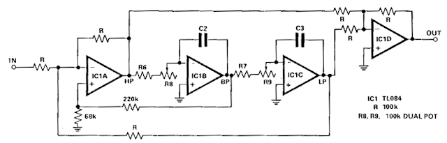
Build an Audio notch filter 2
Build an Audio notch filter 2 Circuit Diagram. With the schema shown here the response at one octave off tune is within 10% of the far out response: notch sharpness may be increased or reduced by reducing or increasing.respectively the 68 ohm resistor. Linearity tracking of R8 and R9 has no effect on notch depth. The signals at HP and LP are always in antiphase, notch will always be very deep at the tuned frequency, despite tolerance variations in R6-9 and C2, C3.
Friday, August 22, 2014
Thursday, August 21, 2014
1000W ICs audio amplifier with PA03
This is a series of amplifiers are based on the most high-ic power that I have ever known. Because the output is issued up to 1000 watts with the impedance RL 4Ohm. Current supply 120mA, and 30A output current. Minimum input voltage of about 30V and a maximum voltage up to 150V. This is an audio amplifier that I have come across use ICs that maximum voltage up to 150V and output power up to 1000W , the scheme below gan.
Part List
Resistor
R1 = 10K
R2 = 10K
R3 = 220K
R4 = 0.18R 5W
R5 = 2.2R 2W
R6 = 0.18R 5W
Capacitor
C1 = 1uF
C2 = 1000uF
C3 = 68pF
C4 = 1000uF
Inductor
L1 = 4MH
IC
U1 = PA03
Sunday, August 10, 2014
10 to 14W Class A Audio Amplifier
I have built this amplifier and it does sound good. It requires a preamp as it hasnt got much gain. It requires big heat sinks and a large transformer and a great power supply and careful wiring, but in the end it is xtremely simple and it sounds very good. The zener diode rejects any ripple coming from the power supply, But you still only want a ripple of 10mV max. The ripple reaching the input is amplified, so the zener diode gets rid of that, but whatever ripple there is will still reach the power stage.
10 to 14W Class A Audio Amplifier Circuit Diagram

10 to 14W Class A Audio Amplifier Circuit Diagram

Subscribe to:
Posts (Atom)
