Showing posts with label filter. Show all posts

Thursday, October 30, 2014

Speech Filter Circuit Diagram

In communications receivers and microphone amplifiers for transmitting equipment, there is frequently a need for a narrow, low-frequency band-pass filter that lets only the voice band through. This band is usually defined to be the portion of the audio frequency spectrum between approximately 300 Hz and 3300 Hz. In order to implement such a filter, we have calculated the values for two fifth-order Butterworth filters having these corner frequencies and connected them in series. The result is a band-pass filter for the desired pass-band with a skirt steepness of 100 dB/decade.  The first opamp (IC1) acts as a buffer.

Speech Filter Image :

 
image


The circuit can be powered by a unipolar supply voltage between 5 V and 18 V, which is a broad enough range that it should always be possible to find a suitable voltage when building the filter into existing equipment. The current consumption of the filter is only a few milliampères, which should rarely pose a problem. There is fairly wide selection of suitable candidates for the opamps, since the circuit is not critical in this regard. In addition to the indicated OP27A, you could consider using a TL081N or even an old-fashioned 741.

Speech Filter Circuit diagram : 
Speech-Filter-Circut-Diagram
Speech Filter Circuit Diagram 


Due to unavoidable spreads in component values, the pass-band curve of the filter will never be completely perfect in actual practice. However, the deviations will be very small and in any case inaudible. In the pass-band region, the gain is approximately unity. The printed circuit board design shown here allows the speech filter to be built in a very compact form, which can be an important factor if it must be fitted into existing equipment. You can quickly check the fully assembled circuit by momentarily measuring the voltages at the inputs and out-puts of the three opamps. Half of the supply voltage should be present at all of these locations.

PCB Layout :


Parts LIST:
Resistors:
R1.R2 = 22kΩ
R3,R11,R12,R18,R19 = 100kΩ
R4 = 470Ω
R5 = 150Ω
R6 = 10kΩ
R7 = 18kΩ
R8 = 15kΩ
R9 = 33kΩ
R10 = 82kΩ
R13-R17 = 3kΩ3
Capacitors:
C1,C8,C14,C15 = 100nF
C2 = 1µF MKT
C3-C7,C11 = 22nF
C9 = 33nF
C10 = 18nF
C12 = 10nF
C13 = 4nF7
C16,C17 = 10µF 16V
Semiconductors:
IC1,IC2,IC3 = OP27A, TL081CN
Miscellaneous:
Bt1 = 9-V battery


Author: G.Baars
Read More..

Wednesday, September 10, 2014

Active band reject filter Circuit

A filter with a band-reject characteristic is frequently referred to as a notch filter. A typical schema using a µ 741 is the unity-gain configuration for this type of active filter shown. The filter response curve shown is a second-order band-reject filter with a notch frequency of 3 kHz. The resulting Q of this filter is about 23, with a notch depth of - 31 dB.Although three passive networks are used in this application, the operational amplifier has become a sharply tuned low-frequency filter without the use of inductors or large-value capacitors.

 Active band-reject filter Circuit Diagram

 active band-reject filter circuit diagran

Read More..

Friday, August 29, 2014

Car subwoofer filter

Circuit description:
Here is the circuit diagram of a simple subwoofer filter that can be operated from a 12V DC supply. Such a circuit is very useful in automobile subwoofer applications. The circuit is nothing but a low pass filter whose pass frequency can be adjusted between 60 to 160 Hz. The circuit is designed around the TL072 dual BIFET opamp IC. Out of the two opamps inside the chip, IC1A is wired as a buffer. The left and right audio inputs after mixing is fed to the input of the IC1A using the DPDT switch S1. Switch S1 is the phase control switch which can be used to make the subwoofer in phase with other speakers. When S1 is in position 2, 180 degree phase shift will be induced.POT R7 can be used for controlling the level. IC1B forms the low pass filter whose pass frequency can be controlled by adjusting the dual gang POT R13.

Circuit Features:
  • The circuit can be powered from 12V DC.
  • IC1 must be mounted on a holder.
  • S1 is a DPDT switch.
  • R13 should be a dual gang linear POT.
  • C5 and C6 must be polyester capacitors.
  • POT R13 can be used for adjusting the pass frequency.
  • POT R7 can be used for adjusting the level.
Circuit diagram:

Car subwoofer filter

Read More..

Saturday, August 23, 2014

Build an Audio notch filter 2

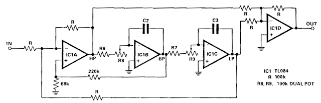
 Build an Audio notch filter 2 Circuit Diagram. With the schema shown here the response at one octave off tune is within 10% of the far out response: notch sharpness may be increased or reduced by reducing or increasing.respectively the 68 ohm resistor. Linearity tracking of R8 and R9 has no effect on notch depth. The signals at HP and LP are always in antiphase, notch will always be very deep at the tuned frequency, despite tolerance variations in R6-9 and C2, C3. 

 Build an Audio notch filter 2 Circuit Diagram


 build an audio notch filter 2 circuit diagram

Read More..