Showing posts with label torch. Show all posts
Showing posts with label torch. Show all posts
Monday, September 8, 2014
Long range Burglar Alarm Using Laser Torch
Laser torch-based burglar alarms normally work in darkness only. But this long-range photoelectric alarm can work reliably in daytime also to warn you against intruders in your big compounds, etc. The alarm comprises laser transmitter and receiver units, which are to be mounted on the opposite pillars of the entry gate. Whenever anyone enters to interrupt the transmitted laser beam falling on the receiver, the buzzer in the receiver schema sounds an alarm.
The range of this burglar alarm is around 30 metres, which means you can place the transmitter and the receiver up to 30 metres apart. Since the laser torch can transmit light up to a distance of 500 metres, this range can be increased by orienting the phototransistor sensor properly. To avoid false triggering by sunlight, mount the phototransistor sensor such that it doesn’t directly face sunlight.
The range of this burglar alarm is around 30 metres, which means you can place the transmitter and the receiver up to 30 metres apart. Since the laser torch can transmit light up to a distance of 500 metres, this range can be increased by orienting the phototransistor sensor properly. To avoid false triggering by sunlight, mount the phototransistor sensor such that it doesn’t directly face sunlight.
Long-range Burglar Alarm Using Laser Torch
Fig. 1: Circuit of laser torch based transmitter
The transmitter schema is powered by 3V DC. The astable multivibrator built around timer 7555 (IC1) produces 5.25kHz frequency. CMOS version of timer 7555 is used for low-voltage operation. The body of the laser torch is connected to the emitter of npn transistor T1 and the spring-loaded lead protruding from inside the torch is connected to the ground.
The receiver schema is powered by 12V DC. It uses photoDarlington 2N5777 (T2) to sense the laser beam transmitted from the laser torch. The output beam signals from photoDarlington are given to the two-stage amplifier followed by switching schema, etc. As long as the laser beam falls on photoDarlington T2, relay RL1 remains un-energised and the buzzer does not sound. Also, LED1 doesn’t glow.
Long-range Burglar Alarm Using Laser Torch
Fig. 2: Receiver schema
Sourced By : EFY Author: Pradeep G.

Saturday, August 9, 2014
A Handy Pen Torch
This easy to construct “Handy pen torch” electronic schema and low component count, uses two power white LEDs for lighting. Low volt (4.8V dc) supply available from the built in rechargeable Ni-Cd battery pack is first converted into two channel (independent) constant current sources by two pieces of the renowned precision adjustable shunt regulator chip LM334 (IC1 and IC2). Around 25mA at 3.6 volt dc is available at the output of these ICs.
This regulated dc supply is used to drive two power white LEDs D4 and D6. Resistors R3 and R5 limits the output current (and hence the light output) of IC1 and IC2 diagram respectively. Besides these components, one red color LED (D2) is included in the main schema which works as a battery charging supply input indicator. Resistor R1 limits the operating current of this LED.
This regulated dc supply is used to drive two power white LEDs D4 and D6. Resistors R3 and R5 limits the output current (and hence the light output) of IC1 and IC2 diagram respectively. Besides these components, one red color LED (D2) is included in the main schema which works as a battery charging supply input indicator. Resistor R1 limits the operating current of this LED.
Pen Torch Electronic Circuit Schematic

Diode D1 works as an input polarity guard cum reverse current flow preventer. Capacitor C1 is a simple buffer for schema stabilization. After succesful construction, preferably on a small piece of general purpose PCB, enclose the whole schema in a suitable and attractive pen torch cabinet. If necessary, drill suitable holes in the cabinet to attatch the dc socket, on/off switch and the input indicator etc. In prototype,commonly available 4.8 volt/500mah Ni-Cd battery pack (for cordless telephones) is used.
One very simple but reliable ac mains powered battery charger schema for the handy pen torch is also included here. Basically the pen torch schema is a constant current charger wired around Transistor T1 (BC636), powered by a 12v/350mA step down transformer and associated componentsD1, D2 and C1.
One very simple but reliable ac mains powered battery charger schema for the handy pen torch is also included here. Basically the pen torch schema is a constant current charger wired around Transistor T1 (BC636), powered by a 12v/350mA step down transformer and associated componentsD1, D2 and C1.
AC mains powered battery charger for the pen torch
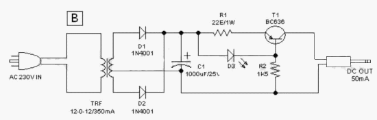
Unregulated 12 volt dc available from the input power convereter schema, comprising step down transformer(TRF), rectifier diodes (D1,D2) and filter capacitor (C1), is fed to T1 through a current limiting resistor R1. Grounded base PNP transistor T1 here works as a constant current generator. With 22 ohm resistor for R1, the charging current available at the output of the charger is near 50mA.
Red LED (D3) provides a fixed voltage reference to the base of T1, with the help of resistor R2. (During charging process, Diode D1 in the main schema prevent reverse current flow from the battery pack when charging input supply is absent.) After construction of the pen torch schema, fit the assembled unit inside a small plastic enclosure for safety and convenience.
Red LED (D3) provides a fixed voltage reference to the base of T1, with the help of resistor R2. (During charging process, Diode D1 in the main schema prevent reverse current flow from the battery pack when charging input supply is absent.) After construction of the pen torch schema, fit the assembled unit inside a small plastic enclosure for safety and convenience.
Circuit Source: DIY Electronics Projects
Subscribe to:
Posts (Atom)
